
Arduino UNO RFID Access Control System with LED Indicators and I2C LCD Display
View and Edit Project In Cirkit Designer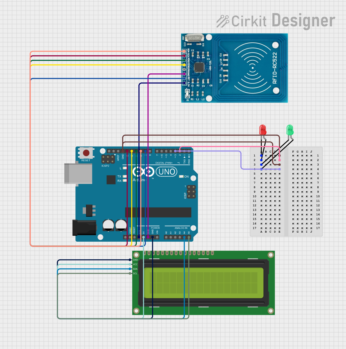
Circuit Documentation
Summary
This circuit involves an Arduino UNO microcontroller interfacing with an RFID-RC522 module, a 16x2 I2C LCD, and two LEDs (one red and one green). The Arduino UNO controls the LEDs and communicates with the RFID module and the LCD display. The LEDs are used to indicate different states, while the RFID module is used for reading RFID tags, and the LCD displays relevant information.
Component List
Arduino UNO
- Description: A microcontroller board based on the ATmega328P.
- Pins: UNUSED, IOREF, Reset, 3.3V, 5V, GND, Vin, A0, A1, A2, A3, A4, A5, SCL, SDA, AREF, D13, D12, D11, D10, D9, D8, D7, D6, D5, D4, D3, D2, D1, D0
RFID-RC522
- Description: A low-cost RFID module that uses the SPI protocol.
- Pins: VCC (3.3V), RST, GND, IRQ, MISO, MOSI, SCK, SDA
16x2 I2C LCD
- Description: A 16x2 character LCD display with I2C interface.
- Pins: GND, VCC, SDA, SCL
LED: Two Pin (green)
- Description: A green LED with two pins.
- Pins: cathode, anode
LED: Two Pin (red)
- Description: A red LED with two pins.
- Pins: cathode, anode
Wiring Details
Arduino UNO
- 3.3V: Connected to VCC (3.3V) of RFID-RC522
- 5V: Connected to VCC of 16x2 I2C LCD
- GND: Connected to GND of RFID-RC522, GND of 16x2 I2C LCD, cathode of red LED, and cathode of green LED
- D2: Connected to anode of red LED
- D3: Connected to anode of green LED
- A4: Connected to SDA of 16x2 I2C LCD
- A5: Connected to SCL of 16x2 I2C LCD
- D9: Connected to RST of RFID-RC522
- D10: Connected to SDA of RFID-RC522
- D11: Connected to MOSI of RFID-RC522
- D12: Connected to MISO of RFID-RC522
- D13: Connected to SCK of RFID-RC522
RFID-RC522
- VCC (3.3V): Connected to 3.3V of Arduino UNO
- RST: Connected to D9 of Arduino UNO
- GND: Connected to GND of Arduino UNO
- SCK: Connected to D13 of Arduino UNO
- MISO: Connected to D12 of Arduino UNO
- MOSI: Connected to D11 of Arduino UNO
- SDA: Connected to D10 of Arduino UNO
16x2 I2C LCD
- VCC: Connected to 5V of Arduino UNO
- GND: Connected to GND of Arduino UNO
- SDA: Connected to A4 of Arduino UNO
- SCL: Connected to A5 of Arduino UNO
LED: Two Pin (green)
- cathode: Connected to GND of Arduino UNO
- anode: Connected to D3 of Arduino UNO
LED: Two Pin (red)
- cathode: Connected to GND of Arduino UNO
- anode: Connected to D2 of Arduino UNO
Code Documentation
Arduino UNO Code
void setup() {
  // Initialisation des broches des LEDs comme sorties
  pinMode(2, OUTPUT); // LED rouge
  pinMode(3, OUTPUT); // LED verte
}

void loop() {
  // Allumer la LED rouge et éteindre la LED verte
  digitalWrite(2, HIGH);
  digitalWrite(3, LOW);
  delay(1000); // Attendre 1 seconde

  // Éteindre la LED rouge et allumer la LED verte
  digitalWrite(2, LOW);
  digitalWrite(3, HIGH);
  delay(1000); // Attendre 1 seconde
}
This code initializes the pins connected to the red and green LEDs as output pins. In the main loop, it alternates between turning the red LED on and the green LED off, and vice versa, with a delay of one second between each state change.