Cirkit Designer
Your all-in-one circuit design IDE
Home /
Project Documentation
ESP32-Controlled Dual Motor Driver Circuit
Circuit Documentation
Summary of the Circuit
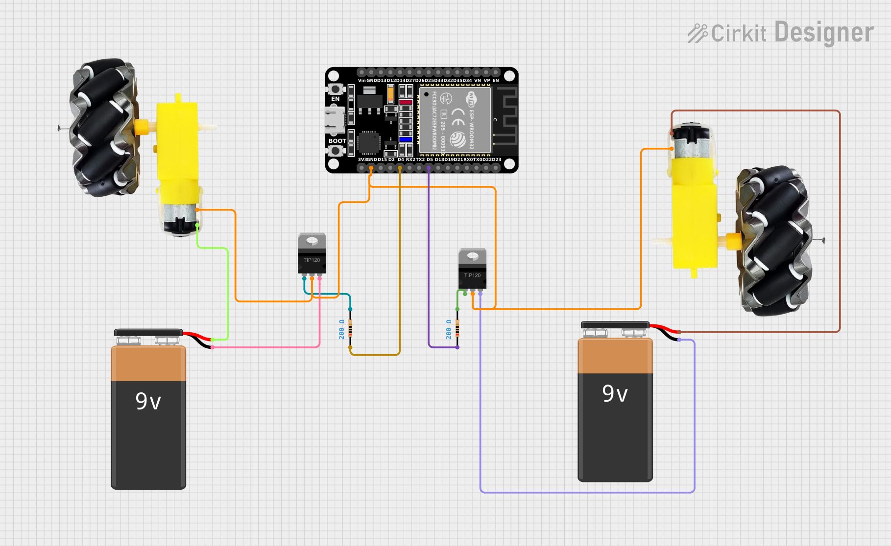
This circuit appears to be designed to control a pair of motors with wheels using an ESP32 microcontroller and TIP120 Darlington Transistors. The ESP32 is used to provide control signals to the transistors, which in turn switch the motors on and off. Each motor is powered by a separate 9V battery. The circuit includes resistors for base current limiting on the transistors.
Component List
ESP32 (30 pin)
- Description: A microcontroller with WiFi and Bluetooth capabilities, featuring a wide range of GPIO pins.
- Pins: EN, VP, VN, D34, D35, D32, D33, D25, D26, D27, D14, D12, D13, GND, Vin, D23, D22, TX0, RX0, D21, D19, D18, D5, TX2, RX2, D4, D2, D15, 3V3
Motor and Wheels (x2)
- Description: A set of motors attached to wheels, used for movement in robotics applications.
- Pins: vcc, GND
9V Battery (x2)
- Description: A standard 9V battery used to provide power to the motors.
- Pins: -, +
TIP120 Hi-Current Darlington Transistor (x2)
- Description: A high-current Darlington transistor used for switching high-power loads such as motors.
- Pins: BASE, COLLECTOR, EMITTER
Resistor (x2)
- Description: A passive component used to limit current or divide voltages.
- Resistance: 200 Ohms
- Pins: pin1, pin2
Wiring Details
ESP32 (30 pin)
- D5 connected to Resistor (pin1)
- D4 connected to Resistor (pin1)
- GND connected to Motor and Wheels (GND), TIP120 Transistor (COLLECTOR), and Motor and Wheels (GND)
Motor and Wheels
- vcc connected to 9V Battery (+)
- GND connected to ESP32 (GND)
9V Battery
- (+) connected to Motor and Wheels (vcc)
- (-) connected to TIP120 Transistor (EMITTER)
TIP120 Hi-Current Darlington Transistor
- BASE connected to Resistor (pin2)
- COLLECTOR connected to ESP32 (GND)
- EMITTER connected to 9V Battery (-)
Resistor
- pin1 connected to ESP32 (D5 or D4)
- pin2 connected to TIP120 Transistor (BASE)
Documented Code
sketch.ino
void setup() {
  // put your setup code here, to run once:

}

void loop() {
  // put your main code here, to run repeatedly:

}
documentation.txt
(No additional documentation provided)
Please note that the actual functionality of the code will depend on the specific requirements of the project. The provided code template is a starting point and will need to be filled in with logic to control the motors via the GPIO pins connected to the TIP120 transistors.