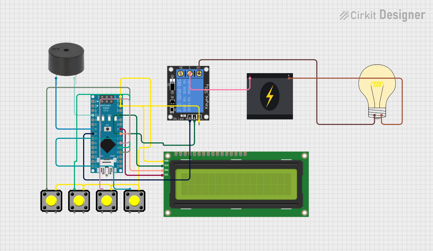
Arduino Nano Controlled Timer Relay with LCD Interface and Buzzer Feedback

Circuit Documentation
Summary
This circuit is designed to control a relay that switches a 240V power source to a bulb, with the relay being controlled by an Arduino Nano microcontroller. The Arduino Nano also interfaces with an I2C LCD 16x2 screen for display purposes and monitors multiple pushbuttons for user input. A buzzer provides audible feedback. The circuit is powered by a 5V supply, which is distributed to the components that require it.
Component List
1-Channel Relay (5V 10A)
- Description: A relay capable of switching high voltage (240V) loads with a 5V control signal.
- Pins: NC (Normally Closed), signal, C (Common), power, NO (Normally Open), ground
I2C LCD 16x2 Screen
- Description: A 16x2 character LCD display with an I2C interface for displaying text and numbers.
- Pins: SCL, SDA, VCC (5V), GND, VDD, VO, RS, RW, E, D0-D7 (Data pins), BLA (Backlight Anode), BLK (Backlight Cathode)
Pushbutton
- Description: A momentary pushbutton used for user input.
- Pins: Pin 1, Pin 2, Pin 3, Pin 4
Bulb
- Description: An electric light bulb that is controlled by the relay.
- Pins: positive, negative
Buzzer
- Description: An audible signaling device that provides feedback when activated.
- Pins: PIN, GND
Arduino Nano
- Description: A small, complete, and breadboard-friendly microcontroller board based on the ATmega328P.
- Pins: D1/TX, D0/RX, RESET, GND, D2-D13, VIN, 5V, A0-A7, AREF, 3V3
240v Power Source
- Description: A power source that provides 240V AC.
- Pins: Live, Neutral
Wiring Details
1-Channel Relay (5V 10A)
- Signal: Connected to Arduino Nano D5
- Power: Connected to Arduino Nano 5V
- Ground: Connected to Arduino Nano GND
- C (Common): Connected to 240v Power Source Live
- NO (Normally Open): Connected to bulb positive
I2C LCD 16x2 Screen
- SCL: Connected to Arduino Nano A5
- SDA: Connected to Arduino Nano A4
- VCC (5V): Connected to Arduino Nano 5V
- GND: Connected to Arduino Nano GND
Pushbuttons
- Pin 1: Connected to Arduino Nano A0, A1, A2, A3 (one pushbutton per pin)
- Pin 4: All connected to Arduino Nano GND
Bulb
- Positive: Connected to 1-Channel Relay NO
- Negative: Connected to 240v Power Source Neutral
Buzzer
- PIN: Connected to Arduino Nano D4
- GND: Connected to Arduino Nano GND
Documented Code
#include <LiquidCrystal.h> // Include LiquidCrystal library for LCD
#include <Keypad.h> // Include Keypad library for keypad input

// Define pins for components
const int buzzerPin = 2;
const int relayPin = 3;
const int lcdPin1 = 4;
const int lcdPin2 = 5;
const int lcdPin3 = 6;
const int lcdPin4 = 7;
const int lcdPin5 = 8;
const int lcdPin6 = 9;
const int switch1Pin = 10;
const int switch2Pin = 11;
const int switch3Pin = 12;
const int switch4Pin = 13;

// Initialize LCD and keypad
LiquidCrystal lcd(lcdPin1, lcdPin2, lcdPin3, lcdPin4, lcdPin5, lcdPin6);
const byte ROWS = 4;
const byte COLS = 4;
char keys[ROWS][COLS] = {
  {'1', '2', '3', 'A'},
  {'4', '5', '6', 'B'},
  {'7', '8', '9', 'C'},
  {'*', '0', '#', 'D'}
};
byte rowPins[ROWS] = {0, 1, 2, 3};
byte colPins[COLS] = {14, 15, 16, 17};
Keypad keypad = Keypad(makeKeymap(keys), rowPins, colPins, ROWS, COLS);

// Global variables
int timerMinutes = 0;
bool timerActive = false;
bool lightOn = false;
unsigned long lastTime = 0;

void setup() {
  // Initialize pins
  pinMode(buzzerPin, OUTPUT);
  pinMode(relayPin, OUTPUT);
  pinMode(switch1Pin, INPUT_PULLUP);
  pinMode(switch2Pin, INPUT_PULLUP);
  pinMode(switch3Pin, INPUT_PULLUP);
  pinMode(switch4Pin, INPUT_PULLUP);

  // Initialize LCD
  lcd.begin(16, 2);
  lcd.print("Timer: 00:00");
}

void loop() {
  char key = keypad.getKey();

  if (key == '1') {
    timerMinutes += 10;
  } else if (key == '2') {
    timerMinutes += 60;
  } else if (key == '3') {
    timerMinutes -= 1;
    if (timerMinutes < 0) {
      timerMinutes = 0;
    }
  } else if (key == '4') {
    timerActive = !timerActive;
    if (timerActive) {
      lastTime = millis();
    } else {
      timerMinutes = 0;
    }
  }

  // Update timer display
  int hours = timerMinutes / 60;
  int minutes = timerMinutes % 60;
  lcd.setCursor(6, 0);
  lcd.print(hours, DEC);
  lcd.print(":");
  lcd.print(minutes, DEC);

  // Check if timer is active and time has elapsed
  if (timerActive && millis() - lastTime >= timerMinutes * 60000) {
    lightOn = true;
    digitalWrite(relayPin, HIGH);
  }

  // Turn off light after 24 hours
  if (lightOn && millis() - lastTime >= 24 * 60 * 60 * 1000) {
    lightOn = false;
    digitalWrite(relayPin, LOW);
    timerMinutes = 0;
    timerActive = false;
  }

  // Play buzzer for feedback
  if (lightOn) {
    digitalWrite(buzzerPin, HIGH);
  } else {
    digitalWrite(buzzerPin, LOW);
  }
}
This code is designed to run on an Arduino Nano and controls the relay, buzzer, and LCD based on input from a keypad. It includes a timer function that can be set and activated using the keypad. When the timer is active and the set time elapses, the relay is turned on, which in turn switches on the bulb. The buzzer provides audible feedback when the light is on. The LCD displays the current timer setting.