
ESP32-Based Environmental Monitoring System with I2C LCD Display
View and Edit Project In Cirkit Designer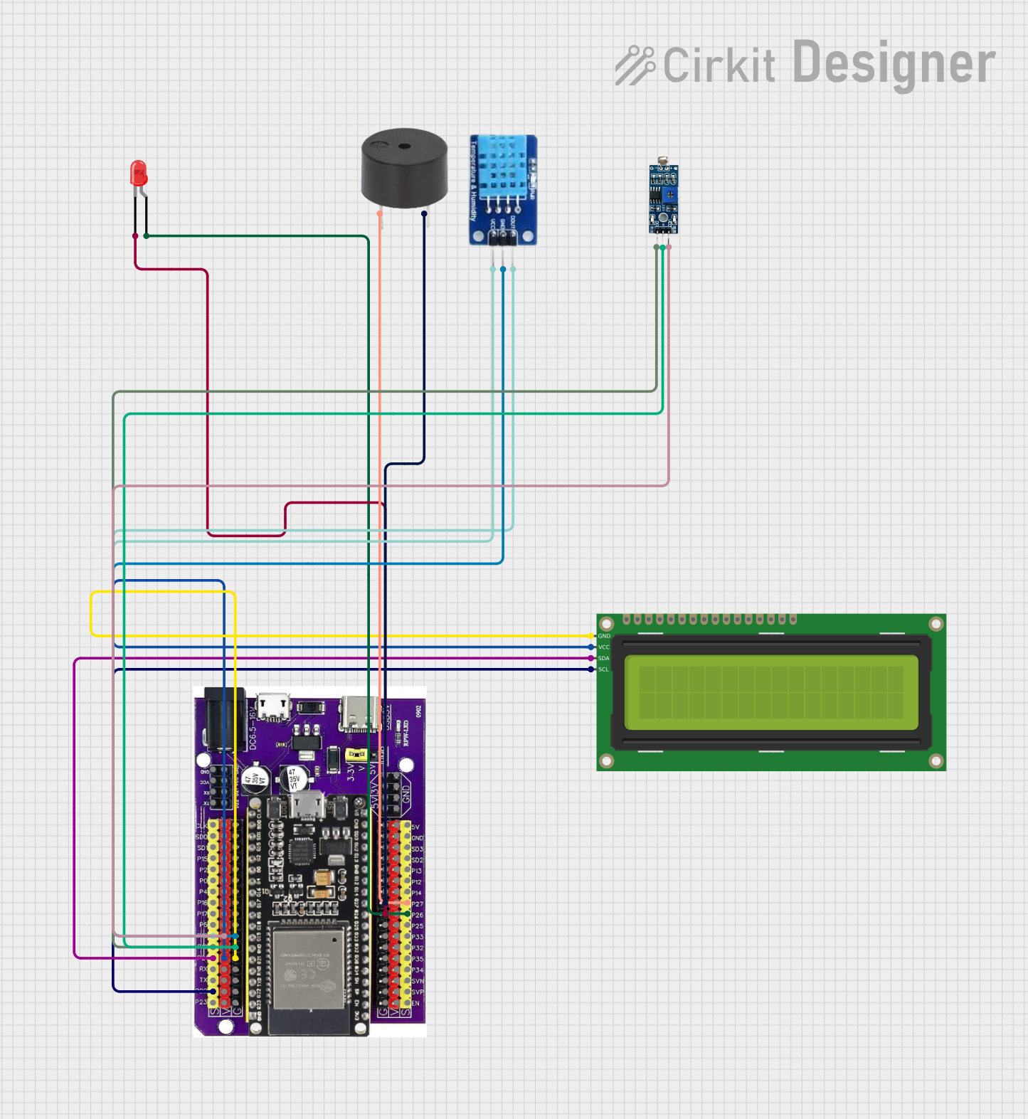
Circuit Documentation
Summary of the Circuit
This circuit integrates various components with an ESP32 microcontroller on a baseboard to perform a range of functions. The ESP32 serves as the central processing unit, interfacing with a DHT11 temperature and humidity sensor, a buzzer, a red LED, an LDR (Light Dependent Resistor) module, and a 16x2 I2C LCD display. The circuit is designed to monitor environmental conditions and provide visual and auditory feedback based on sensor readings.
Component List
ESP32 on Baseboard
- Description: A microcontroller board based on the ESP32 chip, which is a powerful Wi-Fi and Bluetooth enabled MCU.
- Purpose: Acts as the central controller for the circuit, interfacing with all other components.
DHT11
- Description: A basic, low-cost digital temperature and humidity sensor.
- Purpose: Measures the ambient temperature and humidity.
Buzzer
- Description: An electromechanical component that produces sound.
- Purpose: Provides auditory signals or alerts.
LED: Two Pin (red)
- Description: A basic red light-emitting diode.
- Purpose: Acts as a visual indicator.
LDR Module 3 pin
- Description: A module with a light-dependent resistor that changes resistance with light levels.
- Purpose: Senses the ambient light intensity.
16x2 I2C LCD
- Description: A liquid crystal display capable of displaying 16 characters per line across 2 lines, with an I2C interface.
- Purpose: Displays information such as sensor readings or status messages.
Wiring Details
ESP32 on Baseboard
- GPIO22: Connected to SCL pin of the 16x2 I2C LCD.
- GPIO21: Connected to SDA pin of the 16x2 I2C LCD.
- GPIO19: Connected to DO pin of the LDR Module.
- GPIO18: Connected to DATA pin of the DHT11.
- V: Connected to VCC pins of the 16x2 I2C LCD and LDR Module.
- G: Connected to GND pins of the 16x2 I2C LCD, LDR Module, DHT11, red LED, and buzzer.
- GPIO26: Connected to the anode of the red LED.
- GPIO27: Connected to the PIN of the buzzer.
DHT11
- DATA: Connected to GPIO18 of the ESP32 on Baseboard.
- VCC: Connected to V of the ESP32 on Baseboard.
- GND: Connected to G of the ESP32 on Baseboard.
Buzzer
- PIN: Connected to GPIO27 of the ESP32 on Baseboard.
- GND: Connected to G of the ESP32 on Baseboard.
LED: Two Pin (red)
- Anode: Connected to GPIO26 of the ESP32 on Baseboard.
- Cathode: Connected to G of the ESP32 on Baseboard.
LDR Module 3 pin
- VCC: Connected to V of the ESP32 on Baseboard.
- GND: Connected to G of the ESP32 on Baseboard.
- DO: Connected to GPIO19 of the ESP32 on Baseboard.
16x2 I2C LCD
- GND: Connected to G of the ESP32 on Baseboard.
- VCC: Connected to V of the ESP32 on Baseboard.
- SDA: Connected to GPIO21 of the ESP32 on Baseboard.
- SCL: Connected to GPIO22 of the ESP32 on Baseboard.
Documented Code
No code has been provided for the microcontrollers in the circuit. To fully utilize the circuit's capabilities, embedded code should be written and uploaded to the ESP32 microcontroller. The code should initialize and read from the DHT11 sensor, control the buzzer and LED based on sensor inputs, read the LDR module's output, and display relevant information on the 16x2 I2C LCD.