
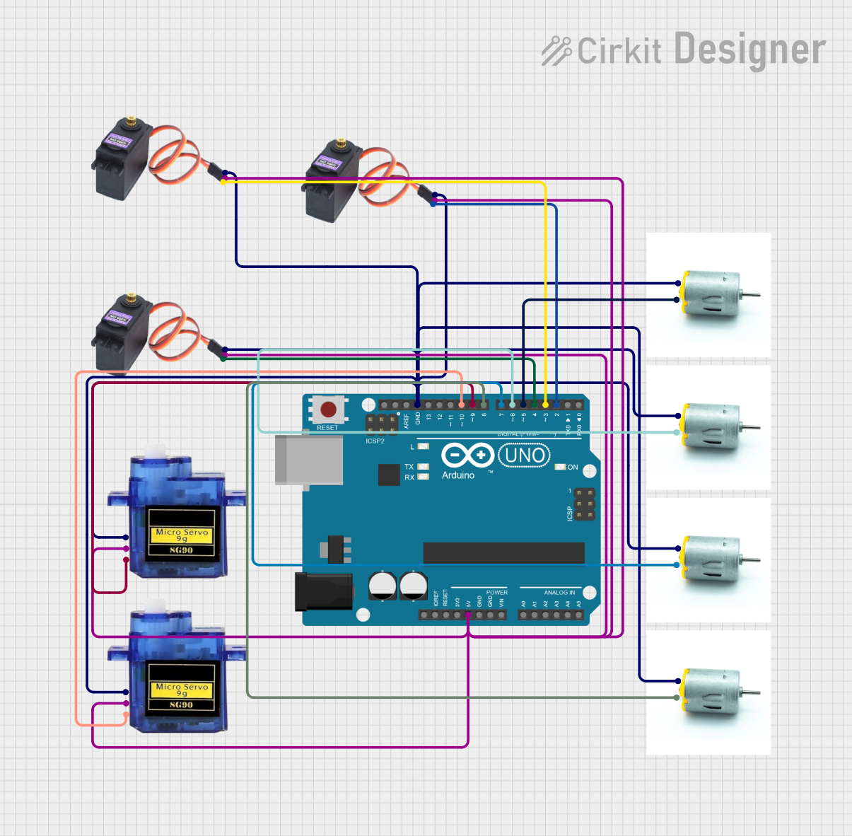
Circuit Documentation
Summary
This circuit involves an Arduino UNO microcontroller controlling multiple motors and servos. The motors are connected to digital pins on the Arduino, while the servos are connected to both power and signal pins. The circuit is designed to control the movement of these motors and servos through the Arduino's digital outputs.
Component List
Motor
- Description: A standard DC motor.
- Pins: Negative, Positive
Micro Servo 9G
- Description: A small servo motor used for precise control of angular position.
- Pins: GND, +5V, PWM
Arduino UNO
- Description: A microcontroller board based on the ATmega328P.
- Pins: UNUSED, IOREF, Reset, 3.3V, 5V, GND, Vin, A0, A1, A2, A3, A4, A5, SCL, SDA, AREF, D13, D12, D11, D10, D9, D8, D7, D6, D5, D4, D3, D2, D1, D0
MG996R
- Description: A high-torque servo motor.
- Pins: GND, VCC, SIG
Wiring Details
Motor
Motor 1
- Negative: Connected to GND
- Positive: Connected to Arduino UNO D6
Motor 2
- Negative: Connected to GND
- Positive: Connected to Arduino UNO D5
Motor 3
- Negative: Connected to GND
- Positive: Connected to Arduino UNO D7
Motor 4
- Negative: Connected to GND
- Positive: Connected to Arduino UNO D8
Micro Servo 9G
Micro Servo 9G 1
- GND: Connected to GND
- +5V: Connected to Arduino UNO 5V
- PWM: Connected to Arduino UNO D9
Micro Servo 9G 2
- GND: Connected to GND
- +5V: Connected to Arduino UNO 5V
- PWM: Connected to Arduino UNO D10
MG996R
MG996R 1
- GND: Connected to GND
- VCC: Connected to Arduino UNO 5V
- SIG: Connected to Arduino UNO D4
MG996R 2
- GND: Connected to GND
- VCC: Connected to Arduino UNO 5V
- SIG: Connected to Arduino UNO D3
MG996R 3
- GND: Connected to GND
- VCC: Connected to Arduino UNO 5V
- SIG: Connected to Arduino UNO D2
Documented Code
Arduino UNO Code (sketch.ino)
void setup() {
  // put your setup code here, to run once:

}

void loop() {
  // put your main code here, to run repeatedly:

}
Additional Documentation (documentation.txt)
This documentation provides a comprehensive overview of the circuit, including a summary, detailed component list, wiring details, and the code used in the Arduino UNO microcontroller.