
Arduino-Controlled Automatic Water Pump System with Dual Level Sensing and I2C LCD Feedback
View and Edit Project In Cirkit Designer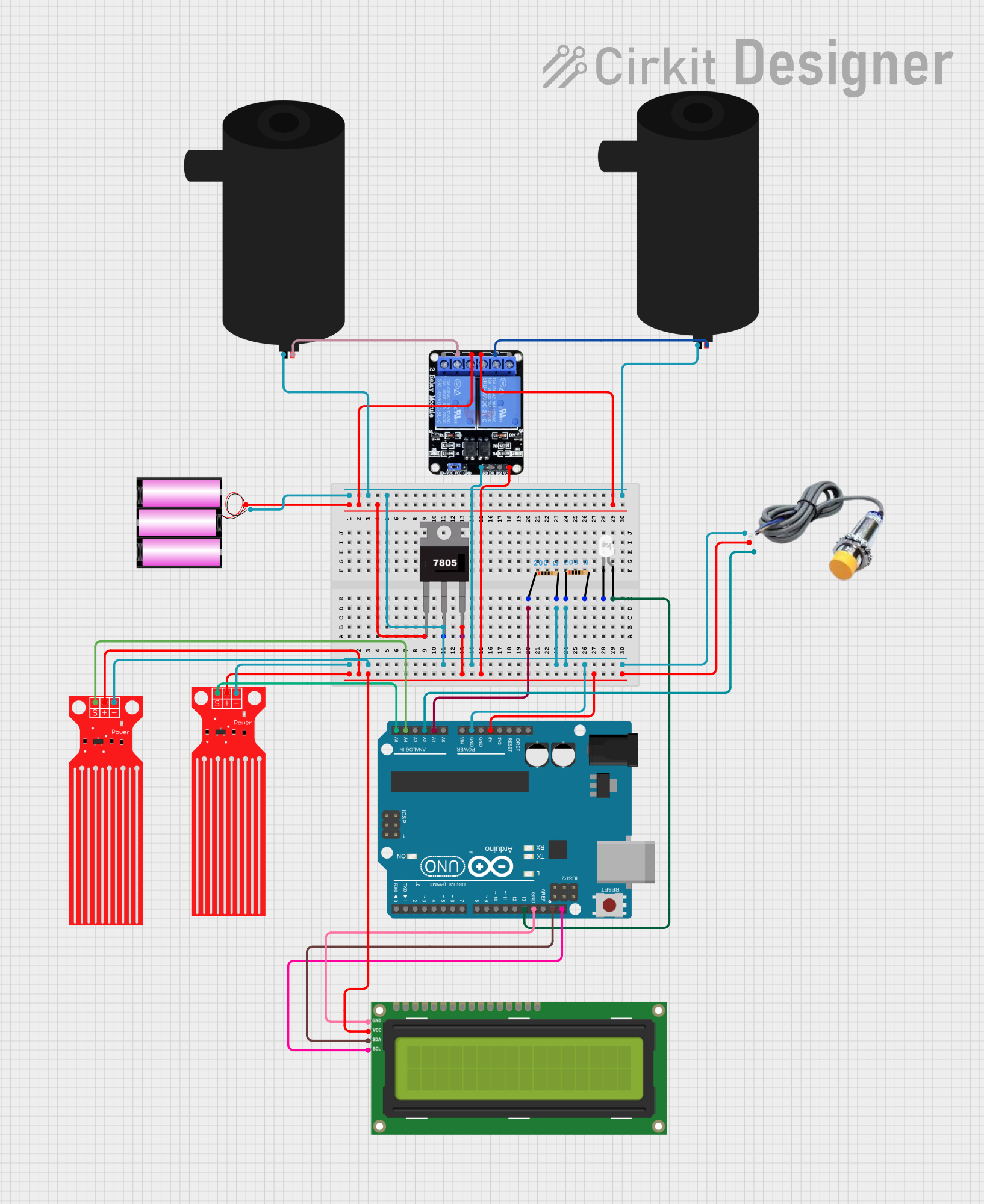
Circuit Documentation
Summary
The circuit described is a Rain Drainage Water Removal System designed to control a water pump based on readings from two water level sensors. It features an Arduino UNO microcontroller, which interfaces with a capacitive sensor, two water level sensors, a two-channel relay module, and an I2C LCD screen. The system also includes an LED indicator and voltage regulation components. The purpose of the circuit is to monitor water levels and activate a water pump to remove excess water, with the system status displayed on the LCD and indicated by the LED.
Component List
Battery (12V)
- Description: Provides the power source for the circuit.
- Pins:
+,-
Two Channel Relay (5V)
- Description: Controls the water pumps by providing isolated switching capabilities.
- Pins:
VCC,IN2,IN1,GND,NC2,C2,NO2,NC1,C1,NO1
Water Level Sensor
- Description: Detects the water level in the environment.
- Pins:
SIG,VCC,GND
Water Pump
- Description: Actuates to remove water based on sensor inputs.
- Pins:
positive,negative
Voltage Regulator (7805)
- Description: Regulates the input voltage to a stable 5V output.
- Pins:
Vin,Gnd,Vout
Arduino UNO
- Description: The main microcontroller unit that controls the system logic.
- Pins:
IOREF,Reset,3.3V,5V,GND,Vin,A0toA5,SCL,SDA,AREF,D13toD0
LED (White)
- Description: Provides a visual indication of the system status.
- Pins:
cathode,anode
Resistor (200 Ohms)
- Description: Limits current to protect components such as LEDs.
- Pins:
pin1,pin2
Capacitive Sensor
- Description: Measures water content in a non-invasive manner.
- Pins:
GND,VCC,SIGNAL
I2C LCD 16x2 Screen
- Description: Displays system status and sensor readings.
- Pins:
SCL,SDA,VCC (5V),GND,VDD,VO,RS,RW,E,D0toD7,BLA,BLK
Wiring Details
Battery (12V)
+connected to Voltage RegulatorVinand RelayNC1,NO2-connected to common ground net
Two Channel Relay (5V)
VCCconnected to 5V netGNDconnected to common ground netC1,C2connected to respective water pumpspositiveNC1,NO2connected to Battery+
Water Level Sensor
SIGconnected to Arduino UNOA5andA4VCCconnected to 5V netGNDconnected to common ground net
Water Pump
positiveconnected to RelayC1,C2negativeconnected to common ground net
Voltage Regulator (7805)
Vinconnected to Battery+Gndconnected to common ground netVoutconnected to 5V net
Arduino UNO
5Vconnected to 5V netGNDconnected to common ground netA1connected to Resistorpin1A2connected to Capacitive SensorSIGNALA4,A5connected to respective Water Level SensorSIGD13connected to LEDanodeSCL,SDAconnected to I2C LCD ScreenSCL,SDA
LED (White)
anodeconnected to Arduino UNOD13cathodeconnected to common ground net
Resistor (200 Ohms)
pin1connected to Arduino UNOA1pin2connected to common ground net
Capacitive Sensor
SIGNALconnected to Arduino UNOA2VCCconnected to 5V netGNDconnected to common ground net
I2C LCD 16x2 Screen
SCLconnected to Arduino UNOSCLSDAconnected to Arduino UNOSDAVCC (5V)connected to 5V netGNDconnected to common ground net
Documented Code
/*
 * Rain Drainage Water Removal System
 *
 * This Arduino sketch controls a water pump based on the readings from two
 * water level sensors. The system displays the water level status on an I2C
 * LCD screen and indicates the pump status using an LED.
 */

#include <Wire.h>
#include <LiquidCrystal_I2C.h>

// Pin definitions
const int waterLevelSensor1Pin = A5;
const int waterLevelSensor2Pin = A4;
const int capacitiveSensorPin = A2;
const int ledPin = 13;
const int relayPin1 = 7;
const int relayPin2 = 8;

// LCD setup
LiquidCrystal_I2C lcd(0x27, 16, 2);

// Timing variables
unsigned long pumpOnTime = 0;
unsigned long pumpOffTime = 0;
bool pumpState = false;

// Display variables
unsigned long lastDisplayUpdate = 0;
const unsigned long displayInterval = 2000; // 2 seconds
int displayState = 0;

void setup() {
  // Initialize serial communication
  Serial.begin(9600);

  // Initialize LCD
  lcd.begin();
  lcd.backlight();

  // Initialize pins
  pinMode(waterLevelSensor1Pin, INPUT);
  pinMode(waterLevelSensor2Pin, INPUT);
  pinMode(capacitiveSensorPin, INPUT);
  pinMode(ledPin, OUTPUT);
  pinMode(relayPin1, OUTPUT);
  pinMode(relayPin2, OUTPUT);

  // Initial state
  digitalWrite(ledPin, LOW);
  digitalWrite(relayPin1, LOW);
  digitalWrite(relayPin2, LOW);
}

void loop() {
  // Read sensor values
  int waterLevel1 = analogRead(waterLevelSensor1Pin);
  int waterLevel2 = analogRead(waterLevelSensor2Pin);
  int capacitiveLevel = analogRead(capacitiveSensorPin);

  // Check water levels and control pump
  if (waterLevel1 > 500 || waterLevel2 > 500 || capacitiveLevel > 500) {
    if (!pumpState) {
      // Turn on pump
      digitalWrite(relayPin1, HIGH);
      digitalWrite(relayPin2, HIGH);
      digitalWrite(ledPin, HIGH);
      pumpOnTime = millis();
      pumpState = true;
    }
  } else {
    if (pumpState) {
      // Turn off pump
      digitalWrite(relayPin1, LOW);
      digitalWrite(relayPin2, LOW);
      digitalWrite(ledPin, LOW);
      pumpOffTime = millis();
      pumpState = false;

      // Print pump on and off times
      Serial.print("Pump was on for: ");
      Serial.print((pumpOffTime - pumpOnTime) / 1000);
      Serial.println(" seconds");
    }
  }

  // Update LCD display
  if (millis() - lastDisplayUpdate > displayInterval) {
    lastDisplayUpdate = millis();
    lcd.clear();
    switch (displayState) {
      case 0:
        lcd.setCursor(0, 0);
        lcd.print("Water1: ");
        lcd.print(waterLevel1);
        lcd.setCursor(0, 1);
        lcd.print("Water2: ");
        lcd.print(waterLevel2);
        break;
      case 1:
        lcd.setCursor(0, 0);
        lcd.print("Capacitive: ");
        lcd.print(capacitiveLevel);
        lcd.setCursor(0, 1);
        lcd.print("Pump: ");
        lcd.print(pumpState ? "ON " : "OFF");
        break;
      case 2:
        lcd.setCursor(0, 0);
        lcd.print("Pump On Time: ");
        lcd.setCursor(0, 1);
        lcd.print((pumpState ? millis() : pumpOffTime) - pumpOnTime);
        lcd.print(" ms");
        break;
    }
    displayState = (displayState + 1) % 3;
  }

  // Delay for stability
  delay(1000);
}
This code is responsible for reading the sensor data, controlling the relay to power the pumps, updating the LCD display, and providing a visual indication of the pump status via an LED. It includes setup and loop functions that initialize the system and handle the main operational logic.