
Arduino 101-Based Multi-Sensor Monitoring System with Wireless Communication
View and Edit Project In Cirkit Designer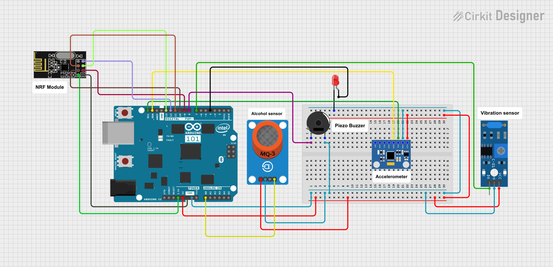
Circuit Documentation
Summary
This circuit integrates various sensors, a communication module, and output devices with an Arduino 101 microcontroller. The primary components include an MQ-3 alcohol sensor, a piezo buzzer, an MPU6050 accelerometer and gyroscope, an SW-420 vibration sensor, an NRF24L01 wireless communication module, and an LED. The Arduino 101 serves as the central processing unit, interfacing with the sensors and modules to perform data acquisition, processing, and wireless communication. The circuit is designed to monitor environmental parameters such as alcohol concentration, motion, and vibration, and to provide alerts or communication based on the sensor readings.
Component List
MQ-3 Alcohol Sensor Breakout
- Pins: VCC, GND, DO, AO
- Description: A sensor for detecting alcohol levels in the air.
Piezo Buzzer
- Pins: pin 1, pin 2
- Description: An electronic device that emits sound when an electric signal is applied.
MPU6050 Accelerometer + Gyroscope
- Pins: INT, AD0, XCL, XDA, SDA, SCL, GND, VCC
- Description: A sensor module that measures acceleration and angular velocity.
SW-420 Vibration Sensor
- Pins: vcc, Ground, Digital output
- Description: A sensor that detects vibrations and movements.
Arduino 101
- Pins: A5/SCL, A4/SDA, AREF, GND, D13/SCK, D12/MISO, D11 PWM/MOSI, D10 PWM/SS, D9 PWM, D8, D7, D6 PWM, D5 PWM, D4, D3 PWM, D2, D1/TX, D0/RX, AIN, ioref, RESET, 3V3, 5V, VIN, A0, A1, A2, A3, ICSP MISO, ICSP SCK, ICSP MOSI
- Description: A microcontroller board based on the Intel Curie module, used for interfacing with various sensors and modules.
LED (Red)
- Pins: cathode, anode
- Description: A two-pin light-emitting diode that emits red light.
NRF24L01 Wireless Communication Module
- Pins: IRQ (not used), MOSI, CSN, VCC (3V), GND, CE, SCK, MISO
- Description: A module for wireless data communication.
Wiring Details
MQ-3 Alcohol Sensor Breakout
- VCC connected to Arduino 101 5V
- GND connected to Arduino 101 GND
- AO connected to Arduino 101 A0
Piezo Buzzer
- pin 1 connected to Arduino 101 D8
- pin 2 connected to Arduino 101 GND
MPU6050 Accelerometer + Gyroscope
- SDA connected to Arduino 101 A4/SDA
- SCL connected to Arduino 101 A5/SCL
- GND connected to Arduino 101 GND
- VCC connected to Arduino 101 5V
SW-420 Vibration Sensor
- vcc connected to Arduino 101 5V
- Ground connected to Arduino 101 GND
- Digital output connected to Arduino 101 D7
LED (Red)
- cathode connected to Arduino 101 GND
- anode connected to Arduino 101 D4
NRF24L01 Wireless Communication Module
- SCK connected to Arduino 101 D13/SCK
- MISO connected to Arduino 101 D12/MISO
- MOSI connected to Arduino 101 D11 PWM/MOSI
- CSN connected to Arduino 101 D10 PWM/SS
- CE connected to Arduino 101 D9 PWM
- VCC (3V) connected to Arduino 101 3V3
- GND connected to Arduino 101 GND
Documented Code
No code has been provided for the microcontroller. The documentation of the code would typically include descriptions of the functions, algorithms, and logic used to interface with the components, process sensor data, and control outputs. Since no code is available, this section cannot be completed.