
Circuit Documentation
Summary
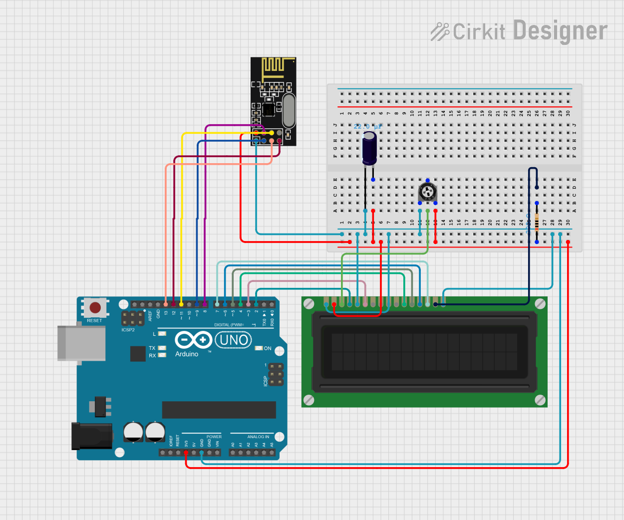
This circuit integrates an Arduino UNO microcontroller with an NRF24L01 wireless transceiver module, an LCD display, an electrolytic capacitor, a resistor, and a trimmer potentiometer. The Arduino UNO serves as the central processing unit, controlling the LCD display and communicating with the NRF24L01 module. The capacitor and resistor are used for power supply filtering and voltage/current adjustments, respectively. The trimmer potentiometer is likely used for adjusting contrast on the LCD display.
Component List
Arduino UNO
- Microcontroller board based on the ATmega328P
- It has 14 digital input/output pins, 6 analog inputs, a 16 MHz quartz crystal, a USB connection, a power jack, an ICSP header, and a reset button.
NRF24L01
- A 2.4GHz wireless transceiver module
- It has configurable data rates and low power consumption features.
Electrolytic Capacitor
- Capacitance: 22 µF (microfarads)
- Typically used for filtering or energy storage in power supply circuits.
LCD Display (16 pin)
- A 16-pin liquid crystal display for user interface
- It can display characters and simple graphics.
Resistor
- Resistance: 200 Ohms
- Used to limit current or divide voltages in electronic circuits.
Trimmer Potentiometer
- Resistance: 10 kOhms
- A variable resistor, often used for adjustment of current or voltage in a circuit.
Wiring Details
Arduino UNO
GNDconnected to common ground net3.3Vconnected to positive voltage net- Digital pins
D2toD13connected to various pins on the NRF24L01 and LCD Display
NRF24L01
GNDconnected to common ground netVCC (3V)connected to positive voltage netCE,CSN,SCK,MISO,MOSIconnected to corresponding digital pins on the Arduino UNO
Electrolytic Capacitor
-(negative) pin connected to common ground net+(positive) pin connected to positive voltage net
LCD Display (16 pin)
VSS,R_W,Kconnected to common ground netVDDconnected to positive voltage netVOconnected to the wiper of the trimmer potentiometerRS,E,DB4toDB7connected to corresponding digital pins on the Arduino UNOAconnected to one end of the resistor
Resistor
- One end connected to the
Apin of the LCD Display - The other end (
pin2) connected to the positive voltage net
Trimmer Potentiometer
leg1connected to common ground netwiperconnected toVOon the LCD Displayleg2connected to positive voltage net
Documented Code
Arduino UNO Code (sketch.ino)
void setup() {
  // put your setup code here, to run once:

}

void loop() {
  // put your main code here, to run repeatedly:

}
Additional Notes (documentation.txt)
No additional code documentation provided.