Arduino UNO-Powered Robotic Vehicle with Ultrasonic and IR Sensors
Circuit Documentation
Summary
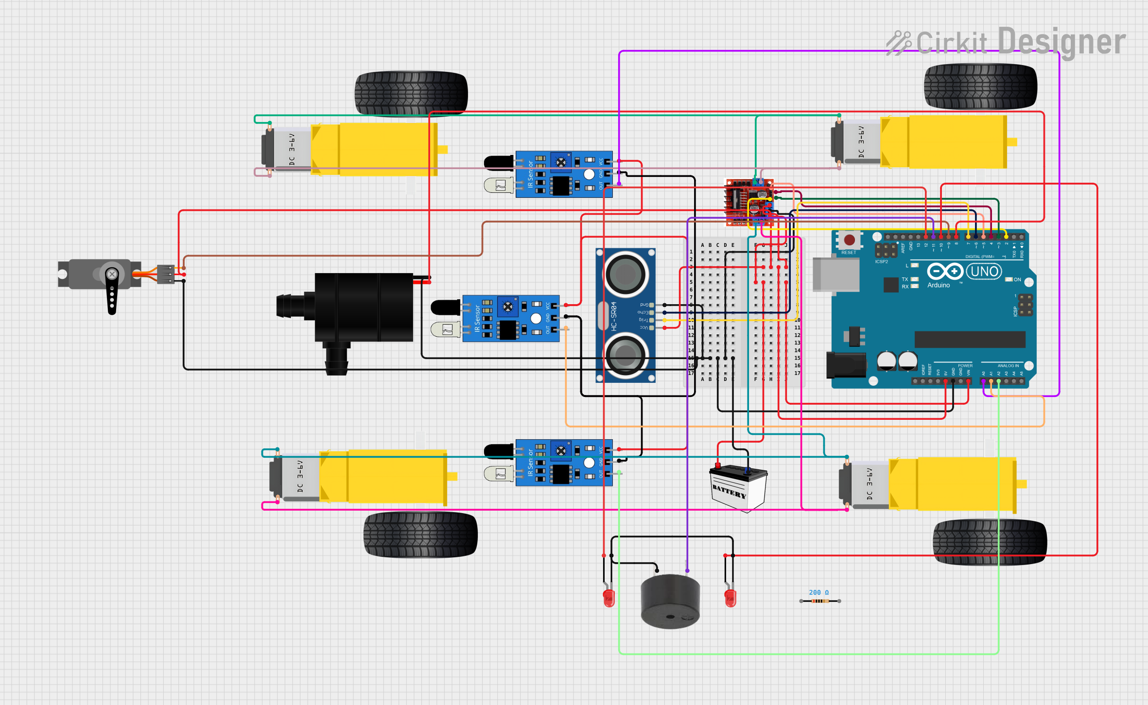
This circuit is designed to interface an Arduino UNO with various sensors, actuators, and a motor driver. It includes ultrasonic sensors for distance measurement, IR sensors for object detection, a servo motor for precise angular movement, DC gearmotors for driving wheels, a motor driver to control the gearmotors, LEDs for visual indication, a buzzer for audio signaling, and a water pump for fluid movement. The circuit is powered by a 12V battery, with voltage regulation provided by the Arduino UNO and the motor driver module.
Component List
Arduino UNO
- Microcontroller board based on the ATmega328P
- Provides I/O pins for interfacing with various components
HC-SR04 Ultrasonic Sensor
- Ultrasonic distance measuring module
- Uses sonar to determine the distance to an object
Gearmotor DC Wheels (Right and Left)
- DC motors with gear reduction
- Used for driving wheels of a robot or vehicle
L298N Motor Driver Controller Board Module
- Dual H-Bridge motor driver
- Capable of driving two DC motors or one stepper motor
12V Battery (Small Size)
- Provides power to the circuit
- 12V output suitable for the motor driver and Arduino VIN
Servo
- Rotary actuator or motor for precise control of angular position
- Controlled by PWM signal
IR Sensor
- Infrared sensors for object detection
- Outputs a digital signal when an object is detected
Water Pump
- Electric pump for moving water or other fluids
- Controlled by a digital signal
LED: Two Pin (Red)
- Visual indicator
- Emits red light when powered
Resistor
- Electrical component that limits or regulates the flow of electrical current
- 200 Ohms resistance
Buzzer
- Audio signaling device
- Emits sound when powered
Wiring Details
Arduino UNO
- 5V pin connected to the 5V power lines of the HC-SR04, L298N, and Servo
- GND pin connected to the ground lines of all components
- Vin pin connected to the 12V Battery VCC
- Digital pins D2 to D12 connected to various components for control signals
HC-SR04 Ultrasonic Sensor
- VCC connected to 5V power line
- GND connected to ground line
- TRIG connected to Arduino pin D7
- ECHO connected to Arduino pin D6
Gearmotor DC Wheels (Right and Left)
- Connected to the L298N motor driver outputs
L298N Motor Driver Controller Board Module
- +12v Power connected to 12V Battery VCC
- +5v Power connected to 5V power line
- Ground connected to ground line
- Input pins 1-4 connected to Arduino pins D2 to D5 for motor control
- Output A/B connected to the Gearmotor DC Wheels
12V Battery (Small Size)
- VCC connected to L298N +12v Power and Arduino Vin
- GND connected to ground line
Servo
- VCC connected to 5V power line
- GND connected to ground line
- PWM connected to Arduino pin D9
IR Sensor
- VCC connected to 5V power line
- GND connected to ground line
- OUT connected to Arduino pins A0, A1, and A2
Water Pump
- VCC connected to Arduino pin D8
- GND connected to ground line
LED: Two Pin (Red)
- Anode connected to Arduino pins D10 and D12
- Cathode connected to ground line through a 200 Ohm resistor
Resistor
- Connected in series with the LED cathodes to limit current
Buzzer
- PIN connected to Arduino pin D11
- GND connected to ground line
Documented Code
// Code for the Arduino UNO
// Filename: sketch.ino

// Define pin connections & constants
const int triggerPin = 7;
const int echoPin = 6;
const int motorInputPins[] = {2, 3, 4, 5};
const int irSensorPins[] = {A0, A1, A2};
const int ledPins[] = {10, 12};
const int servoPin = 9;
const int waterPumpPin = 8;
const int buzzerPin = 11;

void setup() {
  // Initialize all connected pins
  pinMode(triggerPin, OUTPUT);
  pinMode(echoPin, INPUT);
  for (int i = 0; i < 4; i++) {
    pinMode(motorInputPins[i], OUTPUT);
  }
  for (int i = 0; i < 3; i++) {
    pinMode(irSensorPins[i], INPUT);
  }
  for (int i = 0; i < 2; i++) {
    pinMode(ledPins[i], OUTPUT);
  }
  pinMode(servoPin, OUTPUT);
  pinMode(waterPumpPin, OUTPUT);
  pinMode(buzzerPin, OUTPUT);
}

void loop() {
  // Main code loop
  // Add functionality as per application requirements
}
Note: The provided code is a template and does not include specific functionality. It initializes the pins and sets their modes according to the circuit connections. The user should add the actual logic for reading sensors, controlling actuators, and implementing the desired behavior of the system.