
Arduino-Based Renewable Energy Monitoring System with LCD Display
View and Edit Project In Cirkit Designer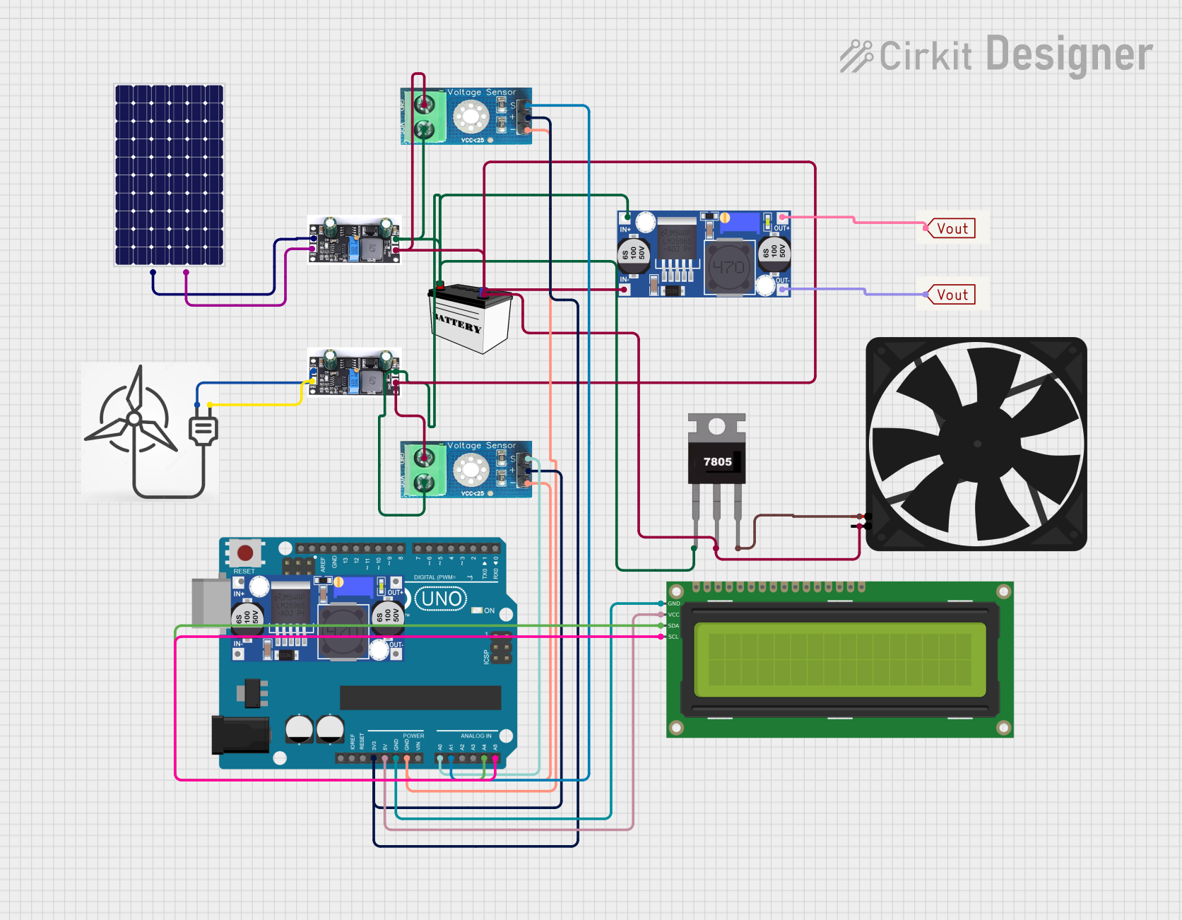
Circuit Documentation
Summary
This circuit integrates renewable energy sources (wind and solar) with a charge controller, battery, voltage sensors, and an Arduino UNO microcontroller. The system monitors the voltage levels from the renewable sources and displays the information on a 16x2 I2C LCD. Additionally, a buck converter and a 7805 voltage regulator are used to manage power distribution, and a fan is included for cooling purposes.
Component List
Wind Turbine
- Pins: +, -
- Description: Converts wind energy into electrical energy.
- Purpose: Provides renewable energy input to the charge controller.
Solar Panel
- Pins: +, -
- Description: Converts solar energy into electrical energy.
- Purpose: Provides renewable energy input to the charge controller.
Charge Controller
- Pins: GND, BAT, Vin
- Description: Manages the charging of the battery from renewable sources.
- Purpose: Ensures safe and efficient charging of the battery.
12V Battery (Small Size)
- Pins: VCC, GND
- Description: Stores electrical energy.
- Purpose: Provides a stable power supply to the circuit.
Voltage Sensor DC 25V
- Pins: +, -, output, gnd, vcc
- Description: Measures voltage levels.
- Purpose: Monitors the voltage from the renewable sources.
Arduino UNO
- Pins: UNUSED, IOREF, Reset, 3.3V, 5V, GND, Vin, A0, A1, A2, A3, A4, A5, SCL, SDA, AREF, D13, D12, D11, D10, D9, D8, D7, D6, D5, D4, D3, D2, D1, D0
- Description: Microcontroller for processing and control.
- Purpose: Reads sensor data and controls the display.
Buck Converter
- Pins: IN+, IN-, OUT+, OUT-
- Description: Steps down voltage.
- Purpose: Provides regulated voltage to the circuit components.
16x2 I2C LCD
- Pins: GND, VCC, SDA, SCL
- Description: Displays information.
- Purpose: Shows voltage readings from the sensors.
Fan
- Pins: GND, 5V
- Description: Provides cooling.
- Purpose: Prevents overheating of components.
7805 Voltage Regulator
- Pins: Vin, Gnd, Vout
- Description: Regulates voltage to 5V.
- Purpose: Provides a stable 5V supply to the fan.
Vout
- Pins: Vout
- Description: Output voltage node.
- Purpose: Collects output voltage from the buck converter.
Wiring Details
Wind Turbine
- + connected to Vin of Charge Controller
- - connected to GND of Charge Controller
Solar Panel
- + connected to Vin of Charge Controller
- - connected to GND of Charge Controller
Charge Controller
- Vin connected to + of Wind Turbine
- GND connected to - of Wind Turbine
- Vin connected to + of Solar Panel
- GND connected to - of Solar Panel
- GND connected to gnd of Voltage Sensor DC 25V
- GND connected to IN- of Buck Converter
- GND connected to GND of Fan
- GND connected to Gnd of 7805
- GND connected to GND of 12V Battery
- BAT connected to vcc of Voltage Sensor DC 25V
- BAT connected to IN+ of Buck Converter
- BAT connected to Vin of 7805
- BAT connected to VCC of 12V Battery
12V Battery (Small Size)
- VCC connected to BAT of Charge Controller
- GND connected to GND of Charge Controller
Voltage Sensor DC 25V
- gnd connected to GND of Charge Controller
- vcc connected to BAT of Charge Controller
- + connected to 3.3V of Arduino UNO
- - connected to GND of Arduino UNO
- output connected to A0 of Arduino UNO
- output connected to A1 of Arduino UNO
Arduino UNO
- 3.3V connected to + of Voltage Sensor DC 25V
- GND connected to - of Voltage Sensor DC 25V
- A0 connected to output of Voltage Sensor DC 25V
- A1 connected to output of Voltage Sensor DC 25V
- 5V connected to VCC of 16x2 I2C LCD
- GND connected to GND of 16x2 I2C LCD
- A4 connected to SDA of 16x2 I2C LCD
- A5 connected to SCL of 16x2 I2C LCD
Buck Converter
- IN- connected to GND of Charge Controller
- IN+ connected to BAT of Charge Controller
- OUT+ connected to Vout of Vout
- OUT- connected to Vout of Vout
16x2 I2C LCD
- VCC connected to 5V of Arduino UNO
- GND connected to GND of Arduino UNO
- SDA connected to A4 of Arduino UNO
- SCL connected to A5 of Arduino UNO
Fan
- GND connected to GND of Charge Controller
- 5V connected to Vout of 7805
7805 Voltage Regulator
- Vin connected to BAT of Charge Controller
- Gnd connected to GND of Charge Controller
- Vout connected to 5V of Fan
Vout
- Vout connected to OUT+ of Buck Converter
- Vout connected to OUT- of Buck Converter
Documented Code
// Define analog input pins for the voltage sensors
#define ANALOG_IN_PIN_1 A0
#define ANALOG_IN_PIN_2 A1

// Floats for ADC voltage & Input voltage
float adc_voltage_1 = 0.0;
float in_voltage_1 = 0.0;
float adc_voltage_2 = 0.0;
float in_voltage_2 = 0.0;

// Floats for resistor values in divider (in ohms)
float R1 = 30000.0;
float R2 = 7500.0;

// Float for Reference Voltage
float ref_voltage = 5.0;

// Integers for ADC values
int adc_value_1 = 0;
int adc_value_2 = 0;

void setup() {
  // Setup Serial Monitor
  Serial.begin(9600);
}

void loop() {
  // Read the Analog Input from the first voltage sensor
  adc_value_1 = analogRead(ANALOG_IN_PIN_1);

  // Determine voltage at ADC input for the first sensor
  adc_voltage_1 = (adc_value_1 * ref_voltage) / 1024.0;

  // Calculate voltage at divider input for the first sensor
  in_voltage_1 = adc_voltage_1 * (R1 + R2) / R2;

  // Print results to Serial Monitor to 2 decimal places for the first sensor
  Serial.print("Input Voltage 1 = ");
  Serial.println(in_voltage_1, 2);

  // Read the Analog Input from the second voltage sensor
  adc_value_2 = analogRead(ANALOG_IN_PIN_2);

  // Determine voltage at ADC input for the second sensor
  adc_voltage_2 = (adc_value_2 * ref_voltage) / 1024.0;

  // Calculate voltage at divider input for the second sensor
  in_voltage_2 = adc_voltage_2 * (R1 + R2) / R2;

  // Print results to Serial Monitor to 2 decimal places for the second sensor
  Serial.print("Input Voltage 2 = ");
  Serial.println(in_voltage_2, 2);

  // Short delay
  delay(500);
}
This code reads the voltage levels from two voltage sensors connected to the Arduino UNO and prints the readings to the Serial Monitor. The voltage readings are calculated based on the ADC values and the resistor values in the voltage divider circuit.