
Circuit Documentation
Summary
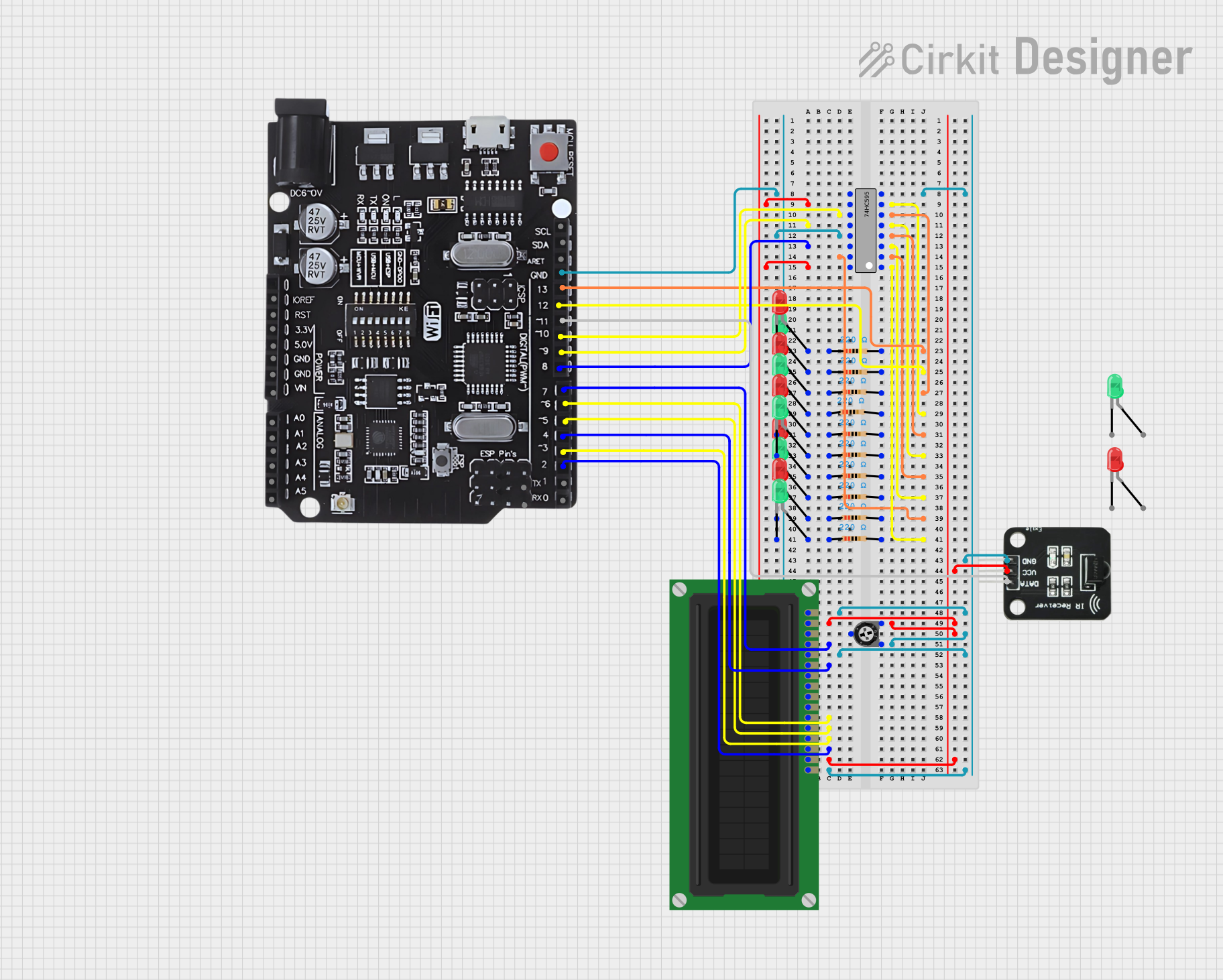
This circuit integrates a variety of components including an Arduino UNO with WiFi capability, multiple LEDs, resistors, a 74HC595 shift register, an LCD display, a trimmer potentiometer, and an IR receiver. The circuit is designed to control LEDs, display information on the LCD, and receive input from an IR receiver. The Arduino UNO serves as the central microcontroller, interfacing with the shift register to control the LEDs and managing the LCD display for output. The trimmer potentiometer is used to adjust the contrast of the LCD display. The IR receiver allows the circuit to respond to infrared signals, potentially from a remote control.
Component List
Microcontroller
- Arduino UNO+WiFi R3 ATmega328P+Node MCU ESP8266 CH340G: A microcontroller board with WiFi capability that serves as the brain of the circuit.
LEDs
- LED: Two Pin (green): A basic green LED for visual indication.
- LED: Two Pin (red): A basic red LED for visual indication.
Resistors
- Resistor: A 220 Ohm resistor used to limit current through the LEDs.
Shift Register
- 74HC595: An 8-bit shift register that expands the digital outputs of the microcontroller.
Display
- LCD Display (16 pin): A 16-pin LCD display used for showing information.
Potentiometer
- Trimmer Potentiometer: A 10k Ohm adjustable resistor used for setting the LCD contrast.
IR Receiver
- IR Receiver: A component that receives infrared signals for remote control functionality.
Wiring Details
Arduino UNO+WiFi R3 ATmega328P+Node MCU ESP8266 CH340G
- Digital pins 2-13 are used for interfacing with the LCD display and the 74HC595 shift register.
- The GND pin is connected to the common ground of the circuit.
LEDs (green and red)
- The anode of each LED is connected to a 220 Ohm resistor.
- The cathode of each LED is connected to the 74HC595 shift register or to the ground through the Arduino for common ground.
Resistors
- Each 220 Ohm resistor is connected in series with an LED to limit the current.
74HC595 Shift Register
- The Q0-Q7 outputs are connected to the anodes of the LEDs through resistors.
- The GND and MR (SRCLR) pins are connected to the ground.
- The VCC pin is connected to a positive voltage supply.
- The SH_CP (SRCLK), ST_CP (RCLK), and DS (DATA) pins are connected to the Arduino for control signals.
LCD Display (16 pin)
- The VSS pin is connected to the ground.
- The VDD and A pins are connected to a positive voltage supply.
- The VO pin is connected to the wiper of the trimmer potentiometer for contrast adjustment.
- The RS, E, DB4-DB7 pins are connected to the Arduino for data and control signals.
- The R_W and K pins are connected to the ground.
Trimmer Potentiometer
- The leg1 is connected to the ground.
- The wiper is connected to the VO pin of the LCD display.
- The leg2 is connected to a positive voltage supply.
IR Receiver
- The DATA pin is connected to the Arduino for signal output.
- The VCC pin is connected to a positive voltage supply.
- The GND pin is connected to the common ground of the circuit.
Documented Code
Since no code was provided, this section is left blank. Normally, this section would include the embedded code for the microcontroller, with comments explaining the functionality and the connections to the hardware components.