
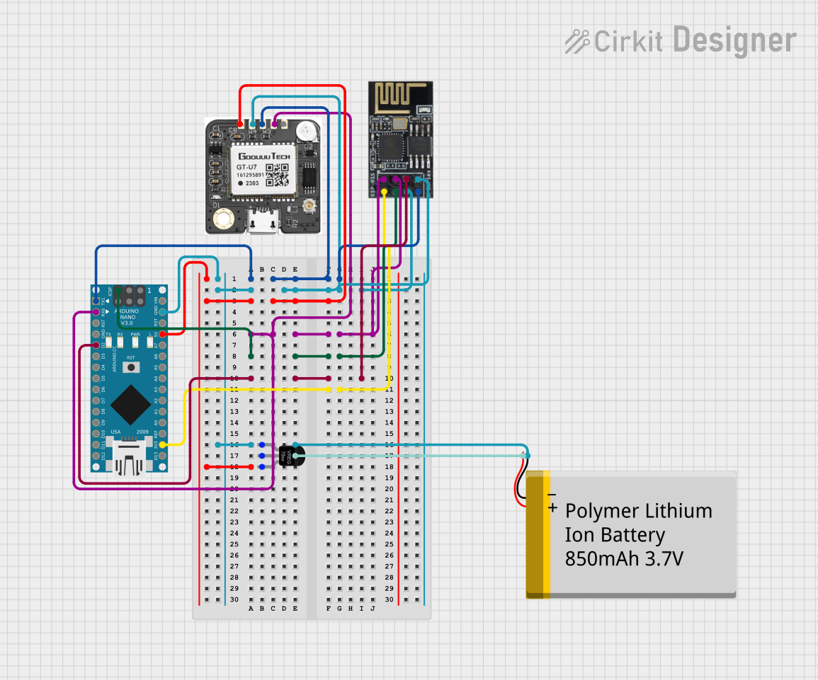
Circuit Documentation
Summary
This circuit is a GPS tracker that utilizes an Arduino Nano, an ESP8266-01 WiFi module, a Neo 6M GPS module, a voltage regulator, and a Polymer Lithium Ion Battery. The Arduino Nano serves as the main microcontroller, interfacing with the GPS module to obtain location data and the WiFi module to transmit this data. The voltage regulator ensures that the components receive the correct voltage levels from the battery.
Component List
Arduino Nano
- Description: A small, complete, and breadboard-friendly board based on the ATmega328P.
- Pins: D1/TX, D0/RX, RESET, GND, D2, D3, D4, D5, D6, D7, D8, D9, D10, D11/MOSI, D12/MISO, VIN, 5V, A7, A6, A5, A4, A3, A2, A1, A0, AREF, 3V3, D13/SCK
Wifi module ESP8266-01
- Description: A self-contained SOC with integrated TCP/IP protocol stack that can give any microcontroller access to your WiFi network.
- Pins: RX, GPIO0, GPIO2, GND, +3V3, Reset, CH-PD Chip power down, TX
Neo 6M GPS
- Description: A GPS module that provides location data.
- Pins: VCC, GND, RXD, TXD, PPS
Voltage Regulator
- Description: A component that regulates the voltage to a desired level.
- Pins: GND, IN, OUT
Polymer Lithium Ion Battery - 850mAh
- Description: A rechargeable battery that provides power to the circuit.
- Pins: GND, VCC
Wiring Details
Arduino Nano
- D1/TX connected to TX of Wifi module ESP8266-01 and RXD of Neo 6M GPS
- D0/RX connected to RX and GPIO0 of Wifi module ESP8266-01 and TXD of Neo 6M GPS
- RESET connected to Reset of Wifi module ESP8266-01
- GND connected to GND of Wifi module ESP8266-01, Neo 6M GPS, Voltage Regulator, and Polymer Lithium Ion Battery
- D2 connected to GPIO2 of Wifi module ESP8266-01
- 3V3 connected to +3V3 of Wifi module ESP8266-01
- 5V connected to OUT of Voltage Regulator
Wifi module ESP8266-01
- TX connected to D1/TX of Arduino Nano and RXD of Neo 6M GPS
- RX and GPIO0 connected to D0/RX of Arduino Nano and TXD of Neo 6M GPS
- Reset connected to RESET of Arduino Nano
- GND connected to GND of Arduino Nano, Neo 6M GPS, Voltage Regulator, and Polymer Lithium Ion Battery
- GPIO2 connected to D2 of Arduino Nano
- +3V3 connected to 3V3 of Arduino Nano
- CH-PD Chip power down connected to GND
Neo 6M GPS
- RXD connected to TX of Wifi module ESP8266-01 and D1/TX of Arduino Nano
- TXD connected to RX and GPIO0 of Wifi module ESP8266-01 and D0/RX of Arduino Nano
- GND connected to GND of Arduino Nano, Wifi module ESP8266-01, Voltage Regulator, and Polymer Lithium Ion Battery
- VCC connected to OUT of Voltage Regulator
Voltage Regulator
- IN connected to VCC of Polymer Lithium Ion Battery
- OUT connected to 5V of Arduino Nano and VCC of Neo 6M GPS
- GND connected to GND of Arduino Nano, Wifi module ESP8266-01, Neo 6M GPS, and Polymer Lithium Ion Battery
Polymer Lithium Ion Battery - 850mAh
- VCC connected to IN of Voltage Regulator
- GND connected to GND of Arduino Nano, Wifi module ESP8266-01, Neo 6M GPS, and Voltage Regulator
Code Documentation
Arduino Nano Code
#include <TinyGPS++.h>
#include <SoftwareSerial.h>

TinyGPSPlus gps;
SoftwareSerial gpsSerial(4, 3);  // RX, TX

void setup() {
  Serial.begin(9600);
  gpsSerial.begin(9600);
  Serial.println("GPS Tracker Starting...");
}

void loop() {
  while (gpsSerial.available() > 0) {
    if (gps.encode(gpsSerial.read())) {
      if (gps.location.isValid()) {
        Serial.print("Latitude: ");
        Serial.println(gps.location.lat(), 6);
        Serial.print("Longitude: ");
        Serial.println(gps.location.lng(), 6);
      }
    }
  }
}
This code initializes the GPS module and reads the location data. If the location data is valid, it prints the latitude and longitude to the serial monitor. The TinyGPSPlus library is used to parse the GPS data, and SoftwareSerial is used to communicate with the GPS module. The GPS module is connected to pins 4 (RX) and 3 (TX) of the Arduino Nano.