
ESP32-Based Fingerprint Access Control System with Solenoid Lock and IR Sensor
View and Edit Project In Cirkit Designer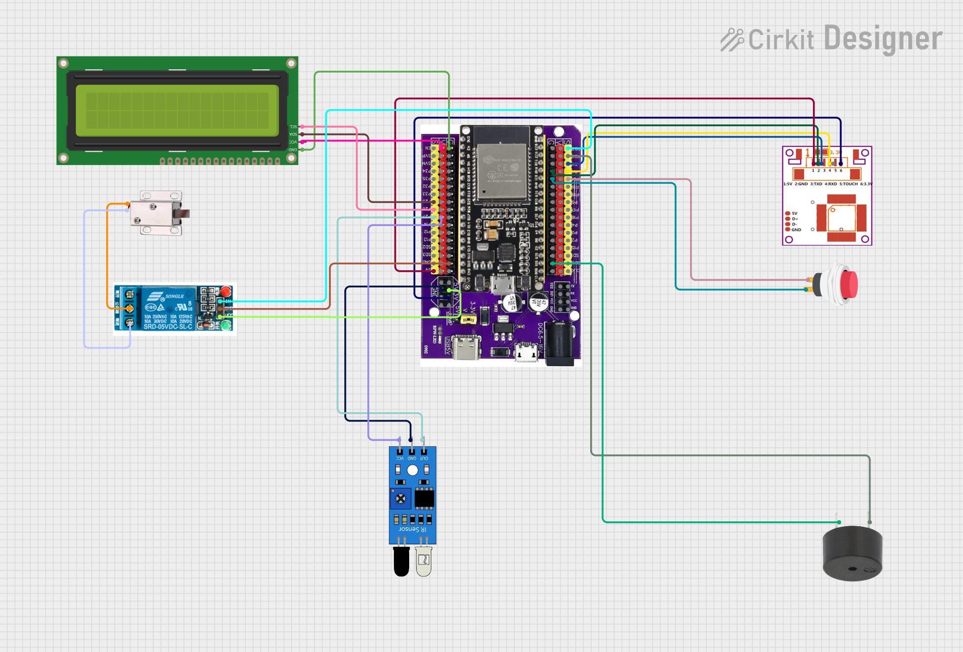
Circuit Documentation
Summary of the Circuit
This circuit is designed to interface an ESP32 microcontroller with various peripherals including a fingerprint sensor, a relay, an I2C LCD, a solenoid lock, a push switch, an IR sensor, and a buzzer. The ESP32 serves as the central processing unit, controlling the relay which in turn controls the power to the solenoid lock. The fingerprint sensor is used for biometric authentication, the I2C LCD displays information, the push switch provides manual input, the IR sensor detects proximity, and the buzzer provides audio feedback.
Component List
ESP32 on Baseboard
- Microcontroller with WiFi and Bluetooth capabilities.
- Provides GPIO pins for interfacing with other components.
R307 Fingerprint Sensor
- Biometric sensor for fingerprint detection and authentication.
5V Relay
- Electromechanical switch that allows the ESP32 to control higher power devices like the solenoid lock.
16x2 I2C LCD
- Alphanumeric liquid crystal display for showing information, interfaced via the I2C protocol.
12V Solenoid Lock
- Electrically actuated lock that can be controlled by the relay.
2Pin Push Switch
- Manual switch that provides a digital input to the ESP32.
IR Sensor
- Infrared sensor used for proximity detection.
Buzzer
- Audio signaling device that emits a tone when powered.
Wiring Details
ESP32 on Baseboard
- GPIO23 connected to Relay In
- GPIO22 connected to Buzzer PIN
- GPIO1/TX connected to Fingerprint Sensor TX
- GPIO3/RX connected to Fingerprint Sensor RX
- GPIO21 connected to Push Switch Input +
- GPIO25 connected to LCD SDA
- GPIO26 connected to LCD SCL
- GPIO27 connected to IR Sensor out
- 5V connected to Relay VCC and Fingerprint Sensor VCC
- 3V connected to Fingerprint Sensor 3.3V
- GND connected to Fingerprint Sensor GND, Push Switch Output +, Buzzer GND, LCD GND, Relay GND, IR Sensor gnd
R307 Fingerprint Sensor
- TX connected to ESP32 GPIO1/TX
- RX connected to ESP32 GPIO3/RX
- VCC connected to ESP32 5V
- GND connected to ESP32 GND
- 3.3V connected to ESP32 3V
5V Relay
- In connected to ESP32 GPIO23
- VCC connected to ESP32 5V
- GND connected to ESP32 GND
- Common terminal connected to Solenoid Lock VCC
- Normally Closed connected to Solenoid Lock GND
16x2 I2C LCD
- VCC connected to ESP32 V
- GND connected to ESP32 G
- SDA connected to ESP32 GPIO25
- SCL connected to ESP32 GPIO26
12V Solenoid Lock
- VCC connected to Relay Common terminal
- GND connected to Relay Normally Closed
2Pin Push Switch
- Input + connected to ESP32 GPIO21
- Output + connected to ESP32 G
IR Sensor
- out connected to ESP32 GPIO27
- vcc connected to ESP32 V
- gnd connected to ESP32 GND
Buzzer
- PIN connected to ESP32 GPIO22
- GND connected to ESP32 G
Documented Code
No code has been provided for the microcontrollers in the circuit. The code would typically include initialization of the GPIO pins, setup of the I2C interface for the LCD, serial communication setup for the fingerprint sensor, and logic for reading the push switch and IR sensor states, as well as controlling the relay and buzzer based on the inputs and sensor data.