
Arduino UNO RFID Access Control System with Servo, RGB LED, Buzzer, and LCD Feedback
View and Edit Project In Cirkit Designer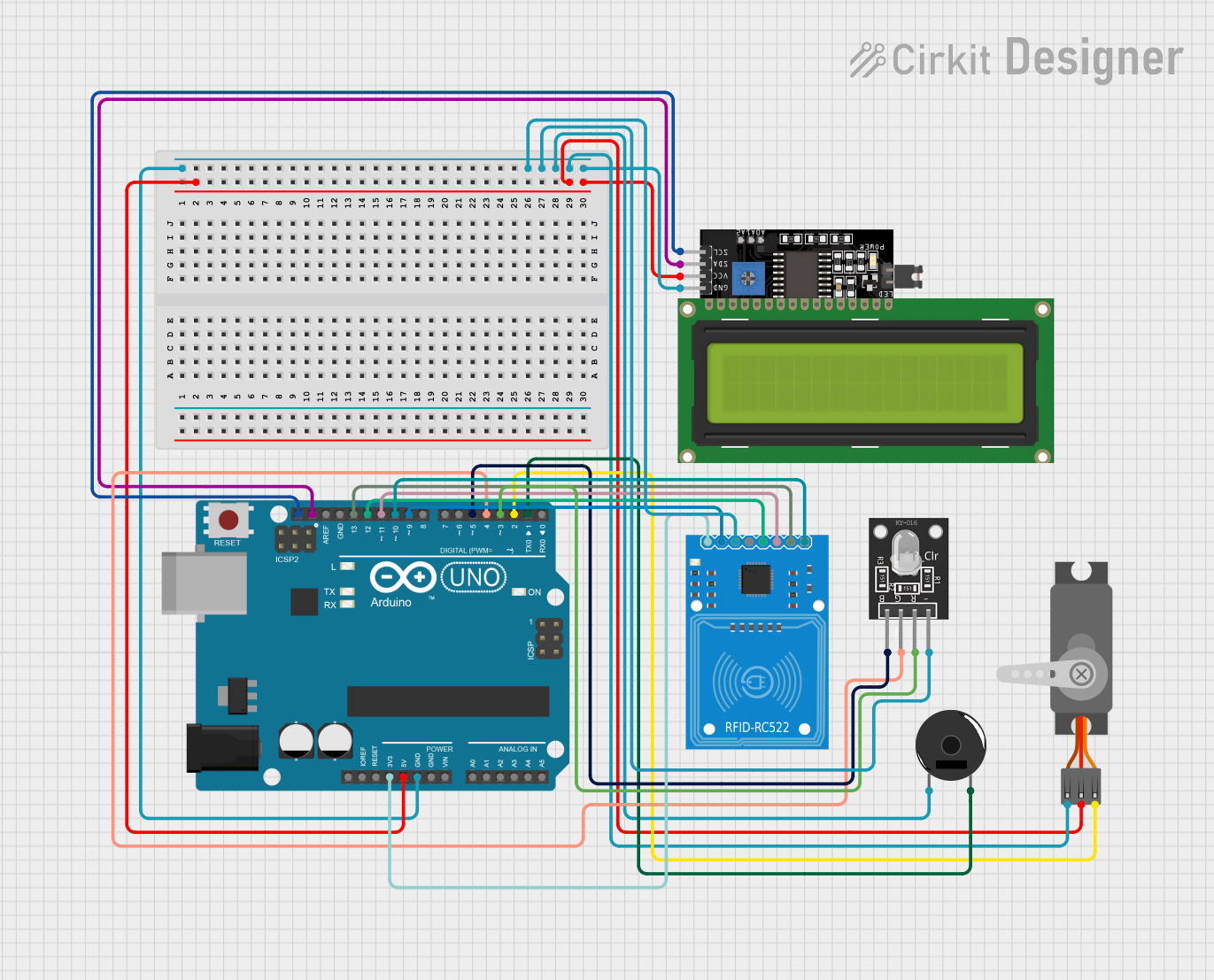
Circuit Documentation
Summary of the Circuit
This circuit is designed to interface with multiple peripherals including an RFID reader, an RGB LED, a piezo buzzer, a servo motor, and an LCD display. The central controller of the circuit is an Arduino UNO microcontroller which communicates with the peripherals to perform specific actions when an RFID card is detected. The RFID reader scans for cards and upon successful detection of a pre-programmed card, the RGB LED lights up in green, the servo motor actuates, and the LCD display shows the message "Accessed". If an incorrect card is detected, the RGB LED turns red and the piezo buzzer emits a tone.
Component List
Arduino UNO
A microcontroller board based on the ATmega328P. It has digital input/output pins, analog inputs, a USB connection for programming the board, a power jack, an ICSP header, and a reset button.
Piezo Buzzer
An electronic device that produces a tone or sound when an electrical signal is applied. It is typically used for audible alerts or alarms.
KY-016 RGB LED
A multicolor light-emitting diode that can produce different colors based on the combination of red, green, and blue light.
RFID-RC522
An RFID reader/writer module that operates at 13.56 MHz. It is commonly used for contactless communication and identification.
LCD Display 16x4 I2C
A liquid crystal display that can show up to 16 characters per line across 4 lines. It uses the I2C protocol for communication, which reduces the number of pins needed for interfacing.
Servo (Wokwi Compatible)
An actuator that can be precisely controlled for position. It is commonly used in robotics for controlling mechanisms like arms, legs, or steering systems.
Wiring Details
Arduino UNO
- GND: Connected to the ground pins of the RFID-RC522, KY-016 RGB LED, Piezo Buzzer, Servo, and LCD Display.
- 5V: Powers the Servo and the VCC of the LCD Display.
- 3.3V: Powers the RFID-RC522.
- SCL: Connected to the SCL pin of the LCD Display.
- SDA: Connected to the SDA pin of the LCD Display.
- D13 (SCK): Connected to the SCK pin of the RFID-RC522.
- D12 (MISO): Connected to the MISO pin of the RFID-RC522.
- D11 (MOSI): Connected to the MOSI pin of the RFID-RC522.
- D10 (SS): Connected to the SDA pin of the RFID-RC522.
- D9 (RST): Connected to the RST pin of the RFID-RC522.
- D5: Connected to the B pin of the KY-016 RGB LED.
- D4: Connected to the G pin of the KY-016 RGB LED.
- D3: Connected to the R pin of the KY-016 RGB LED.
- D2: Connected to the PWM pin of the Servo.
- D1: Connected to pin 2 of the Piezo Buzzer.
Piezo Buzzer
- Pin 1: Connected to the ground (GND) through the common ground network.
- Pin 2: Connected to D1 on the Arduino UNO.
KY-016 RGB LED
- B: Connected to D5 on the Arduino UNO.
- G: Connected to D4 on the Arduino UNO.
- R: Connected to D3 on the Arduino UNO.
- GND: Connected to the ground (GND) through the common ground network.
RFID-RC522
- SDA: Connected to D10 on the Arduino UNO.
- SCK: Connected to D13 on the Arduino UNO.
- MOSI: Connected to D11 on the Arduino UNO.
- MISO: Connected to D12 on the Arduino UNO.
- IRQ: Not connected.
- GND: Connected to the ground (GND) through the common ground network.
- RST: Connected to D9 on the Arduino UNO.
- 3.3V: Connected to the 3.3V output on the Arduino UNO.
LCD Display 16x4 I2C
- SCL: Connected to the SCL pin on the Arduino UNO.
- SDA: Connected to the SDA pin on the Arduino UNO.
- VCC: Connected to the 5V output on the Arduino UNO.
- GND: Connected to the ground (GND) through the common ground network.
Servo (Wokwi Compatible)
- GND: Connected to the ground (GND) through the common ground network.
- V+: Connected to the 5V output on the Arduino UNO.
- PWM: Connected to D2 on the Arduino UNO.
Documented Code
/*
 * This Arduino sketch interfaces with an RFID reader, an RGB LED, a piezo buzzer,
 * a servo motor, and an LCD display. When the correct RFID card is read, the
 * green LED lights up, the servo motor moves, and the LCD displays 'Accessed'.
 */

#include <Wire.h>
#include <LiquidCrystal_I2C.h>
#include <Servo.h>
#include <SPI.h>
#include <MFRC522.h>

#define SS_PIN 10
#define RST_PIN 9
#define SERVO_PIN 2
#define BUZZER_PIN 1
#define RED_PIN 3
#define GREEN_PIN 4
#define BLUE_PIN 5

LiquidCrystal_I2C lcd(0x27, 16, 4);
Servo myservo;
MFRC522 rfid(SS_PIN, RST_PIN);

void setup() {
  Serial.begin(9600);
  SPI.begin();
  rfid.PCD_Init();
  lcd.begin();
  lcd.backlight();
  myservo.attach(SERVO_PIN);
  pinMode(BUZZER_PIN, OUTPUT);
  pinMode(RED_PIN, OUTPUT);
  pinMode(GREEN_PIN, OUTPUT);
  pinMode(BLUE_PIN, OUTPUT);
  digitalWrite(RED_PIN, LOW);
  digitalWrite(GREEN_PIN, LOW);
  digitalWrite(BLUE_PIN, LOW);
}

void loop() {
  if (!rfid.PICC_IsNewCardPresent() || !rfid.PICC_ReadCardSerial()) {
    return;
  }
  String cardID = "";
  for (byte i = 0; i < rfid.uid.size; i++) {
    cardID += String(rfid.uid.uidByte[i], HEX);
  }
  if (cardID == "your_card_id_here") {
    digitalWrite(GREEN_PIN, HIGH);
    lcd.clear();
    lcd.setCursor(0, 0);
    lcd.print("Accessed");
    myservo.write(90);
    delay(2000);
    digitalWrite(GREEN_PIN, LOW);
    myservo.write(0);
  } else {
    digitalWrite(RED_PIN, HIGH);
    tone(BUZZER_PIN, 1000, 500);
    delay(500);
    digitalWrite(RED_PIN, LOW);
  }
  rfid.PICC_HaltA();
  rfid.PCD_StopCrypto1();
}
This code is designed to be uploaded to the Arduino UNO microcontroller. It initializes the connected devices and sets up the main loop to check for RFID card presence, read the card ID, and perform actions based on the card detected. The code uses libraries for the LCD (LiquidCrystal_I2C), servo motor (Servo), and RFID reader (MFRC522). The defined pin constants correspond to the wiring details provided earlier.