Cirkit Designer
Your all-in-one circuit design IDE
Home /
Project Documentation
Arduino UNO-Based Environmental Monitoring System with Wi-Fi Connectivity
Circuit Documentation
Summary
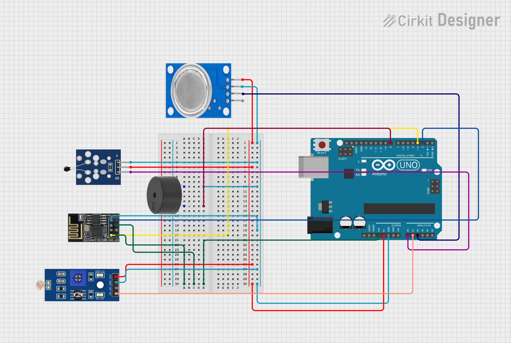
This circuit is designed to monitor environmental conditions using various sensors and communicate the data over Wi-Fi. It includes an Arduino UNO microcontroller, an analog temperature sensor, a gas sensor (MQ135), a light-dependent resistor (LDR), a buzzer, and a Wi-Fi module (ESP8266-01). The Arduino UNO reads data from the sensors and controls the buzzer based on the sensor readings. The data is then sent to a remote server via the Wi-Fi module.
Component List
Analog Temperature Sensor (NTC)
- Description: Measures temperature using a negative temperature coefficient thermistor.
- Pins: GND, VCC, OUT
Arduino UNO
- Description: Microcontroller board based on the ATmega328P.
- Pins: UNUSED, IOREF, Reset, 3.3V, 5V, GND, Vin, A0, A1, A2, A3, A4, A5, SCL, SDA, AREF, D13, D12, D11, D10, D9, D8, D7, D6, D5, D4, D3, D2, D1, D0
Buzzer
- Description: Emits sound when activated.
- Pins: PIN, GND
LDR
- Description: Light-dependent resistor used to measure light intensity.
- Pins: A0, D0, GND, VCC
MQ135
- Description: Gas sensor used to measure air quality.
- Pins: VCC, GND, A0, D0
Wi-Fi Module (ESP8266-01)
- Description: Wi-Fi module used for wireless communication.
- Pins: RX, GPIO0, GPIO2, GND, +3V3, Reset, CH-PD Chip power down, TX
Wiring Details
Analog Temperature Sensor (NTC)
- GND: Connected to GND
- VCC: Connected to 5V
- OUT: Connected to A0 on Arduino UNO
Arduino UNO
- GND: Connected to GND of all other components
- 3.3V: Connected to +3V3 and CH-PD Chip power down on Wi-Fi module
- 5V: Connected to VCC of Analog Temperature Sensor, LDR, and MQ135
- A0: Connected to OUT of Analog Temperature Sensor
- A1: Connected to A0 of LDR
- A2: Connected to A0 of MQ135
- D2: Connected to TX of Wi-Fi module
- D3: Connected to RX of Wi-Fi module
- D8: Connected to PIN of Buzzer
Buzzer
- PIN: Connected to D8 on Arduino UNO
- GND: Connected to GND
LDR
- A0: Connected to A1 on Arduino UNO
- GND: Connected to GND
- VCC: Connected to 5V
MQ135
- VCC: Connected to 5V
- GND: Connected to GND
- A0: Connected to A2 on Arduino UNO
Wi-Fi Module (ESP8266-01)
- RX: Connected to D3 on Arduino UNO
- TX: Connected to D2 on Arduino UNO
- GND: Connected to GND
- +3V3: Connected to 3.3V on Arduino UNO
- CH-PD Chip power down: Connected to 3.3V on Arduino UNO
Documented Code
#include <SoftwareSerial.h>

#define RX 2
#define TX 3

String AP = "DESKTOP-D2KO9SK 3774";       // AP NAME
String PASS = "38t7Y11;";     // AP PASSWORD
String HOST = "fi2.bot-hosting.net"; // API Host
String PORT = "20251";           // API Port
int countTrueCommand;
int countTimeCommand;
boolean found = false;
SoftwareSerial esp8266(RX, TX);

// Pin definitions
#define gassensor A2                              // Pin for gas sensor
#define buzzer 8                                  // Pin for buzzer
#define ntcPin A0                                 // Pin for NTC thermistor
#define LDR A1                                    // Pin for LDR sensor

// MQ-135 Gas Sensor
float R0 = 10.0; // Resistance of the sensor in clean air (in kOhms)

// NTC Thermistor Variables
float Vin = 5.0;     // [V]
float Rt = 10000;    // Resistor value [ohm]
float R0_ntc = 10000; // value of rct in T0 [ohm]
float T0 = 298.15;   // use T0 in Kelvin [K]
float Vout = 0.0;    // Vout in A0
float Rout = 0.0;    // Rout in A0
float T1 = 273.15;   // [K] in datasheet 0º C
float T2 = 373.15;   // [K] in datasheet 100° C
float RT1 = 35563;   // [ohms]  resistance in T1
float RT2 = 549;     // [ohms]   resistance in T2
float beta = 0.0;    // initial parameters [K]
float Rinf = 0.0;    // initial parameters [ohm]
float TempK = 0.0;   // variable output
float TempC = 0.0;   // variable output

void setup() {
  Serial.begin(115200); // Start serial communication
  pinMode(gassensor, INPUT); // Set gas sensor pin as input
  pinMode(buzzer, OUTPUT); // Set buzzer pin as output
  pinMode(ntcPin, INPUT); // Set NTC pin as input
  pinMode(LDR, INPUT); // Set LDR pin as input

  // Parameters for NTC thermistor
  beta = (log(RT1 / RT2)) / ((1 / T1) - (1 / T2));
  Rinf = R0_ntc * exp(-beta / T0);
  esp8266.begin(115200);

  // Initialize ESP8266
  sendCommand("AT", 5, "OK");
  sendCommand("AT+CWMODE=1", 5, "OK");

  // Connect to Wi-Fi
  if (sendCommand("AT+CWJAP=\""+ AP +"\",\""+ PASS +"\"", 20, "OK")) {
    Serial.println("WiFi connected successfully!");
  } else {
    Serial.println("WiFi connection failed.");
  }
}

void loop() {
  // Read gas sensor value
  int gasValue = analogRead(gassensor);

  // Control buzzer based on gas sensor value
  if (gasValue >= 600) {
    digitalWrite(buzzer, HIGH);
  } else {
    digitalWrite(buzzer, LOW);
  }

  // Read NTC thermistor
  Vout = Vin * ((float)(analogRead(ntcPin)) / 1024.0); // calc for ntc
  Rout = (Rt * Vout / (Vin - Vout));
  TempK = (beta / log(Rout / Rinf)); // calc for temperature
  TempC = TempK - 273.15;

  // Print results to serial monitor
  Serial.print("Gas Value: ");
  Serial.print(gasValue);
  Serial.println(" ppm");

  Serial.print("Temperature: ");
  Serial.print(TempC);
  Serial.write(0xdf); // to display ° symbol
  Serial.print("C  ");

  // Read LDR sensor
  int readValue = analogRead(LDR);
  if (readValue > 100) {
    digitalWrite(buzzer, HIGH);
  } else {
    digitalWrite(buzzer, LOW);
  }
   Serial.print("light intensity: ");
  Serial.print(readValue);
  Serial.println(" Candela");

  String postData = "p=" + String(gasValue) + "&t=" + String(TempC) + "&c=" + String(readValue); // Data to send
  String getData = String("POST / HTTP/1.1\r\n") + // Change to your endpoint if necessary
                   "Host: " + HOST + "\r\n" +
                   "Content-Type: application/x-www-form-urlencoded\r\n" +
                   "Content-Length: " + String(postData.length()) + "\r\n" +
                   "Connection: close\r\n\r\n" + // Double CRLF indicates end of headers
                   postData; // Actual data to be sent

  sendCommand("AT+CIPMUX=1", 5, "OK");
  sendCommand("AT+CIPSTART=0,\"TCP\",\"" + HOST + "\"," + PORT, 15, "OK");

  // Prepare to send data
  sendCommand("AT+CIPSEND=0,"