Arduino Nano-Controlled Robotics Platform with IR and Ultrasonic Sensing
Circuit Documentation
Summary
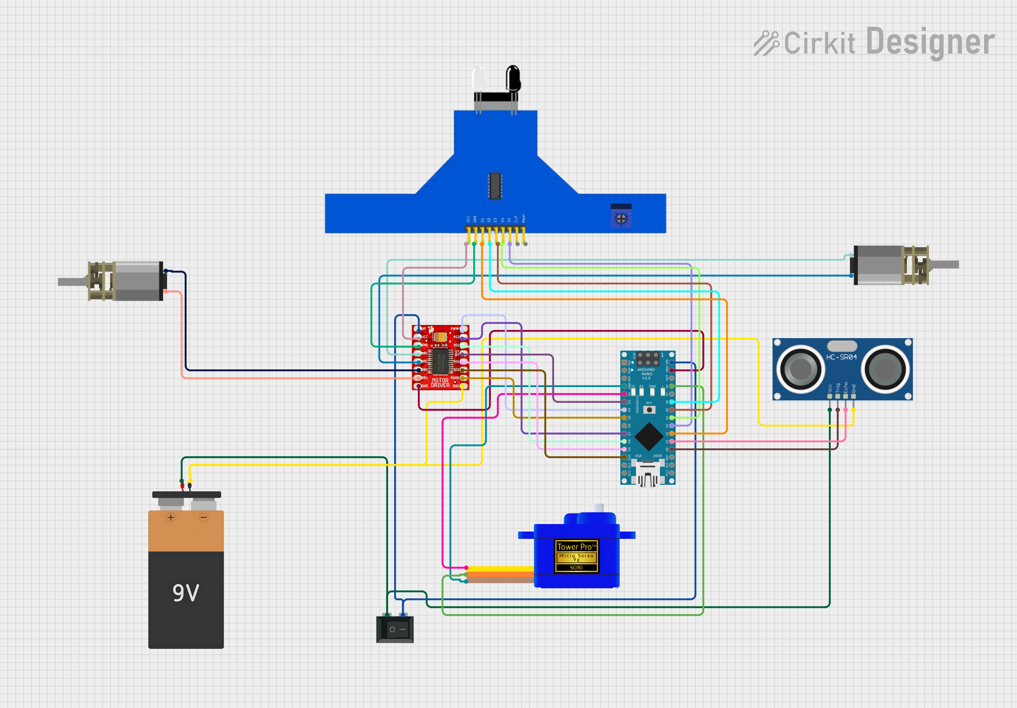
This circuit integrates various components controlled by an Arduino Nano microcontroller to perform a set of functions that likely involve motion control and distance sensing. The circuit includes a motor driver to control two DC Mini Metal Gear Motors, a servomotor for precise angular movement, an ultrasonic sensor for distance measurement, and a 5-channel IR sensor for line tracking or obstacle detection. A 9V battery powers the system, with a rocker switch to control power flow.
Component List
Arduino Nano
- Microcontroller board based on the ATmega328P
- It has a variety of digital and analog I/O pins.
5 Channel IR Sensor
- An array of IR sensors typically used for line tracking or obstacle detection.
DC Mini Metal Gear Motor (x2)
- Small DC motors with gear reduction for increased torque.
TB6612FNG Motor Driver
- A motor driver capable of controlling two DC motors or one stepper motor.
Battery 9V
- Standard 9V battery to power the circuit.
Rocker Switch (SPST)
- A single-pole single-throw switch used to control the power supply to the circuit.
Servomotor SG90
- A small and lightweight servomotor for precise control of motion.
HC-SR04 Ultrasonic Sensor
- A sensor for measuring distances using ultrasonic sound waves.
Wiring Details
Arduino Nano
- GND connected to Servomotor SG90, TB6612FNG Motor Driver, and HC-SR04 Ultrasonic Sensor.
- D2 connected to Servomotor SG90 (SIG).
- D3 connected to TB6612FNG Motor Driver (STBY).
- D4 connected to TB6612FNG Motor Driver (PWMA).
- D5 connected to TB6612FNG Motor Driver (PWMB).
- D7 connected to TB6612FNG Motor Driver (AI2).
- D8 connected to TB6612FNG Motor Driver (AI1).
- D9 connected to TB6612FNG Motor Driver (BI1).
- D10 connected to TB6612FNG Motor Driver (BI2).
- VIN connected to Rocker Switch (SPST) and TB6612FNG Motor Driver (VM).
- 5V connected to Servomotor SG90 (VCC).
- A0-A6 connected to HC-SR04 Ultrasonic Sensor (TRIG, ECHO) and 5 Channel IR Sensor (S1-S5).
5 Channel IR Sensor
- VCC and GND connected to TB6612FNG Motor Driver.
DC Mini Metal Gear Motor
- IN1 and IN2 of each motor connected to TB6612FNG Motor Driver (A01, A02, B01, B02).
TB6612FNG Motor Driver
- GND connected to Arduino Nano, 5 Channel IR Sensor, and Battery 9V.
- VCC connected to 5 Channel IR Sensor.
- VM connected to Arduino Nano (VIN) through Rocker Switch (SPST).
Battery 9V
- VCC and GND connected to Rocker Switch (SPST) and HC-SR04 Ultrasonic Sensor.
Rocker Switch (SPST)
- 1 and 2 connected to Battery 9V (VCC) and Arduino Nano (VIN), respectively.
Servomotor SG90
- SIG connected to Arduino Nano (D2).
- VCC connected to Arduino Nano (5V).
- GND connected to Arduino Nano.
HC-SR04 Ultrasonic Sensor
- VCC connected to Battery 9V through Rocker Switch (SPST).
- TRIG connected to Arduino Nano (A0).
- ECHO connected to Arduino Nano (A1).
- GND connected to Battery 9V.
Documented Code
void setup() {
  // put your setup code here, to run once:

}

void loop() {
  // put your main code here, to run repeatedly:

}
The provided code is a template with empty setup() and loop() functions, which are the entry points for Arduino code. The setup() function is called once when the microcontroller is powered on or reset, and it is used to initialize the system, such as setting pin modes. The loop() function is called repeatedly and contains the main logic of the program. The actual functionality would be implemented within these functions based on the specific requirements of the circuit's application.