
Arduino-Controlled Flame Detection System with Relay-Activated Water Pump and Alert Mechanisms
View and Edit Project In Cirkit Designer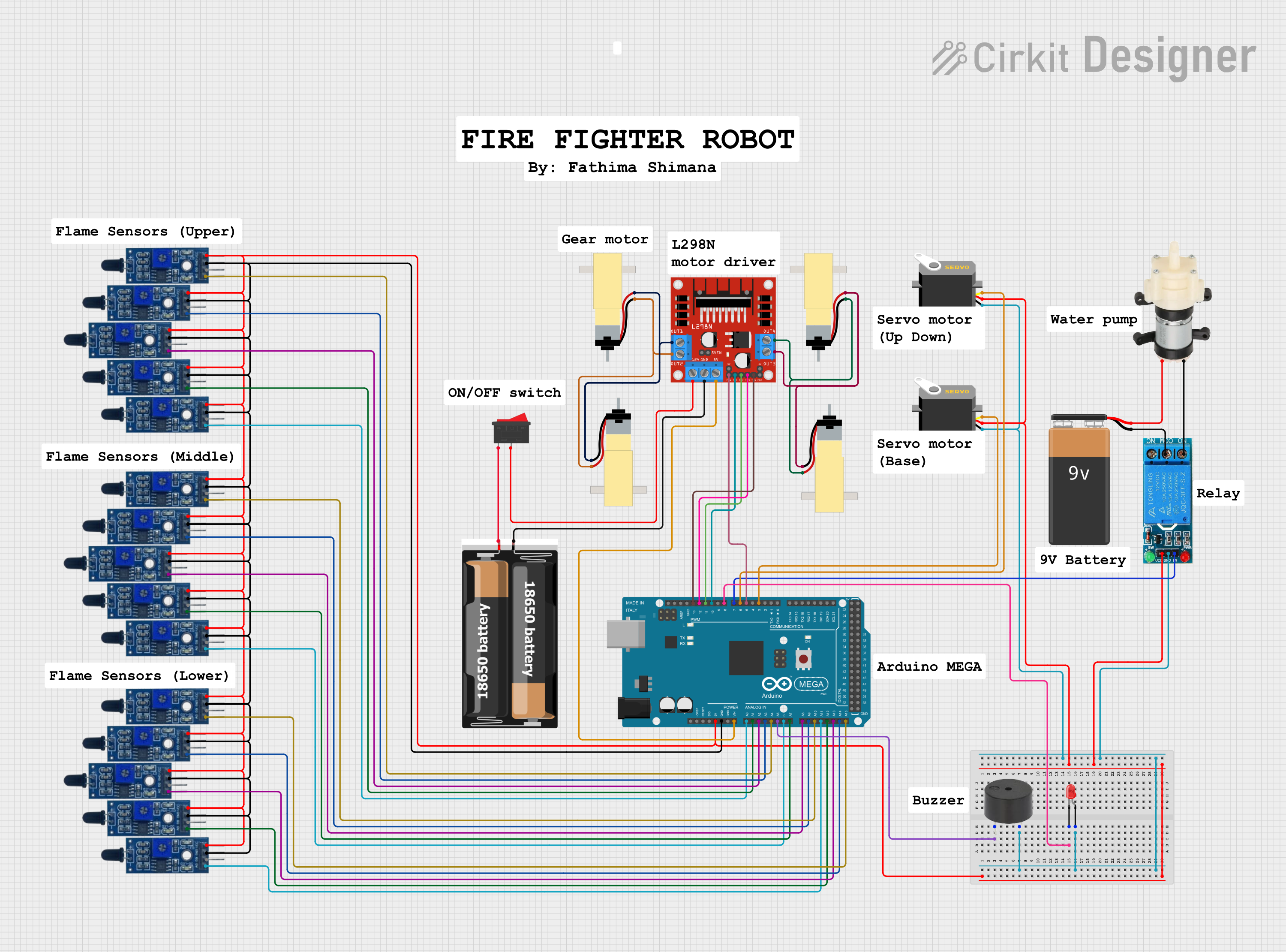
Circuit Documentation
Summary
This document provides a detailed overview of a circuit designed to control various components including servos, gearmotors, a relay, sensors, and a water pump. The circuit is powered by a combination of a 9V battery and a 2x 18650 battery pack. It is controlled by an Arduino Mega 2560, which interfaces with flame sensors, a buzzer, an LED, and a water pump through a relay. The Arduino also controls two servos and drives a set of hobby gearmotors via an L298N motor driver. A rocker switch is included to manage power to the motor driver.
Component List
- Servo: A motor capable of precise position control, typically used in RC applications.
- 2x 18650 Battery Pack: A power source consisting of two 18650 lithium-ion batteries.
- Rocker Switch: A switch to toggle the connection in a circuit.
- Hobby Gearmotor with 48:1 Gearbox: A motor with a gearbox to increase torque output.
- 12V Single Channel Relay: An electrically operated switch that allows controlling high power devices.
- L298N DC Motor Driver: A module capable of driving two DC motors or one stepper motor.
- LED (Red): A two-pin light-emitting diode.
- Arduino Mega 2560: A microcontroller board based on the ATmega2560.
- Flame Sensor: A sensor that can detect fire or other wavelengths of light.
- Mini Diaphragm Water Pump: A pump used for moving water.
- Buzzer: An audio signaling device.
- 9V Battery: A standard 9V battery used for power supply.
Wiring Details
Servo
- Ground: Connected to the common ground net.
- VCC: Connected to the 5V output from the Arduino Mega 2560.
- Pulse: Controlled by the Arduino Mega 2560 (PWM pins D3 and D6).
2x 18650 Battery Pack
- VCC: Connected to the rocker switch.
- Ground: Connected to the common ground net.
Rocker Switch
- Pin 1: Connected to the VCC of the 2x 18650 battery pack.
- Pin 2: Connected to the 12V input of the L298N motor driver.
Hobby Gearmotor with 48:1 Gearbox
- Pin 1 & Pin 2: Connected to the outputs of the L298N motor driver.
12V Single Channel Relay
- NC (Normally Closed): Not connected.
- COM (Common): Connected to the negative terminal of the 9V battery.
- NO (Normally Open): Connected to the negative terminal of the Mini Diaphragm Water Pump.
- IN (Input): Controlled by the Arduino Mega 2560 (pin D7).
- GND (Ground): Connected to the common ground net.
- VCC (Voltage Supply): Connected to the 5V output from the Arduino Mega 2560.
L298N DC Motor Driver
- OUT1, OUT2, OUT3, OUT4: Connected to the pins of the Hobby Gearmotors.
- 12V: Connected to the rocker switch.
- GND: Connected to the common ground net.
- 5V: Connected to the VIN pin of the Arduino Mega 2560.
- ENA, ENB: Controlled by the Arduino Mega 2560 (PWM pins D5).
- IN1, IN2, IN3, IN4: Controlled by the Arduino Mega 2560 (pins D10, D11, D12, D13).
LED (Red)
- Cathode: Connected to the common ground net.
- Anode: Controlled by the Arduino Mega 2560 (pin D8).
Arduino Mega 2560
- Digital and Analog Pins: Various pins are used to control and read from the connected components.
- 5V & GND: Provide power to the flame sensors and the relay.
- VIN: Receives power from the L298N motor driver's 5V output.
Flame Sensor
- VCC: Connected to the 5V output from the Arduino Mega 2560.
- GND: Connected to the common ground net.
- D0: Not connected in this configuration.
- A0: Connected to various analog pins on the Arduino Mega 2560 (A0 to A15).
Mini Diaphragm Water Pump
- Positive (+): Connected to the positive terminal of the 9V battery.
- Negative (-): Connected to the Normally Open (NO) contact of the relay.
Buzzer
- PIN: Controlled by the Arduino Mega 2560 (pin A5).
- GND: Connected to the common ground net.
9V Battery
- Negative (-): Connected to the Common (COM) contact of the relay.
- Positive (+): Connected to the positive terminal of the Mini Diaphragm Water Pump.
Documented Code
Arduino Mega 2560 (sketch.ino)
void setup() {
  // put your setup code here, to run once:

}

void loop() {
  // put your main code here, to run repeatedly:

}
Note: The provided code is a template and does not contain any functional code to control the circuit components. The actual implementation should include initialization of the pins as outputs or inputs, control logic for the motors, servos, relay, and reading from the flame sensors.