
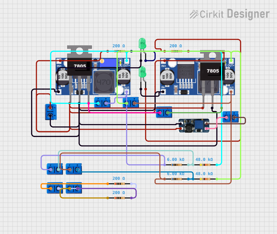
Circuit Documentation
Summary
The circuit in question appears to be a power regulation and distribution system with multiple voltage regulation stages, including buck converters, a boost converter, and linear voltage regulators (7805). It also includes LEDs with current-limiting resistors, which could serve as power indicators or status lights. The circuit is designed to step down or step up the input voltage to different levels suitable for various loads or parts of a larger system.
Component List
Buck Converters
- Description: These components are used to step down the voltage to a lower level. They are efficient and suitable for applications where the input voltage is higher than the desired output voltage.
- Pins: IN+, IN-, OUT+, OUT-
DC-DC Boost Converter
- Description: This component steps up the voltage from a lower level to a higher level. It is used when the output voltage needs to be higher than the available input voltage.
- Pins: VIN-, VIN+, VOUT+, VOUT-
LEDs (Green)
- Description: Light Emitting Diodes (LEDs) are used as visual indicators. Green LEDs are typically used to indicate power or operational status.
- Pins: cathode, anode
Resistors
- Description: Resistors are passive components used to limit current, divide voltages, and perform other functions in a circuit. In this circuit, they are likely used as current-limiting resistors for LEDs and for other voltage regulation purposes.
- Values: Various values including 48k Ohms, 6k Ohms, and 200 Ohms
7805 Voltage Regulators
- Description: These are linear voltage regulators that provide a stable 5V output from a higher input voltage. They are commonly used in electronic circuits to provide a regulated power supply.
- Pins: Vin, Gnd, Vout
Terminal PCB 2 Pin
- Description: These are connectors used for making external connections to the PCB. They provide convenient points to interface the circuit with external devices or power sources.
- Pins: Pin A, Pin B
Wiring Details
Buck Converters
- IN+: Connected to the positive voltage input.
- IN-: Connected to the ground or negative voltage input.
- OUT+: Connected to the positive voltage output.
- OUT-: Connected to the ground or negative voltage output.
DC-DC Boost Converter
- VIN-: Connected to the ground or negative voltage input.
- VIN+: Connected to the positive voltage input.
- VOUT+: Connected to the positive voltage output.
- VOUT-: Connected to the ground or negative voltage output.
LEDs (Green)
- cathode: Connected to the ground or negative side of the circuit.
- anode: Connected to the positive side through a current-limiting resistor.
Resistors
- pin1: One end of the resistor, connected as per circuit requirements.
- pin2: The other end of the resistor, connected as per circuit requirements.
7805 Voltage Regulators
- Vin: Input voltage, higher than 5V.
- Gnd: Ground or negative voltage input.
- Vout: Regulated 5V output voltage.
Terminal PCB 2 Pin
- Pin A: One of the two connection points, used for input or output as per circuit design.
- Pin B: The other connection point, used for input or output as per circuit design.
Documented Code
There is no embedded code provided for any microcontrollers in the circuit. If there are microcontrollers or programmable devices in the circuit, their code would be documented in this section. Since no code is provided, this section remains empty.