
Arduino-Based Rain Detection System with LED and Buzzer Alerts
View and Edit Project In Cirkit Designer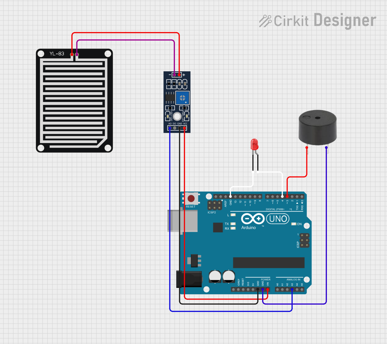
Circuit Documentation
Summary
This circuit is designed to detect rain using a YL-83 Rain Sensor and control various outputs such as an LED and a buzzer using an Arduino UNO. The rain sensor's detection board is connected to its control board, which in turn interfaces with the Arduino. The Arduino processes the sensor data and controls the LED and buzzer accordingly.
Component List
YL-83 Rain Sensor - Detection Board
- Pins: POS, NEG
- Description: This board detects the presence of rain and sends the signal to the control board.
YL-83 Rain Sensor - Control Board
- Pins: VCC, GND, DO, AO, POS, NEG
- Description: This board processes the signal from the detection board and sends an analog output to the Arduino.
Arduino UNO
- Pins: UNUSED, IOREF, Reset, 3.3V, 5V, GND, Vin, A0, A1, A2, A3, A4, A5, SCL, SDA, AREF, D13, D12, D11, D10, D9, D8, D7, D6, D5, D4, D3, D2, D1, D0
- Description: A microcontroller board that processes the input from the rain sensor and controls the LED and buzzer.
LED: Two Pin (red)
- Pins: cathode, anode
- Description: A red LED that lights up based on the Arduino's output.
Buzzer
- Pins: PIN, GND
- Description: A buzzer that sounds based on the Arduino's output.
Wiring Details
YL-83 Rain Sensor - Detection Board
- POS connected to POS of YL-83 Rain Sensor - Control Board
- NEG connected to NEG of YL-83 Rain Sensor - Control Board
YL-83 Rain Sensor - Control Board
- POS connected to POS of YL-83 Rain Sensor - Detection Board
- NEG connected to NEG of YL-83 Rain Sensor - Detection Board
- VCC connected to Vin of Arduino UNO
- GND connected to GND of Arduino UNO
- AO connected to A3 of Arduino UNO
Arduino UNO
- Vin connected to VCC of YL-83 Rain Sensor - Control Board
- GND connected to GND of YL-83 Rain Sensor - Control Board
- GND connected to GND of Buzzer
- GND connected to cathode of LED
- A3 connected to AO of YL-83 Rain Sensor - Control Board
- D4 connected to anode of LED
- D3 connected to PIN of Buzzer
LED: Two Pin (red)
- cathode connected to GND of Arduino UNO
- anode connected to D4 of Arduino UNO
Buzzer
- PIN connected to D3 of Arduino UNO
- GND connected to GND of Arduino UNO
Documented Code
Arduino UNO Code (sketch.ino)
void setup() {
  // put your setup code here, to run once:

}

void loop() {
  // put your main code here, to run repeatedly:

}
Additional Documentation (documentation.txt)