
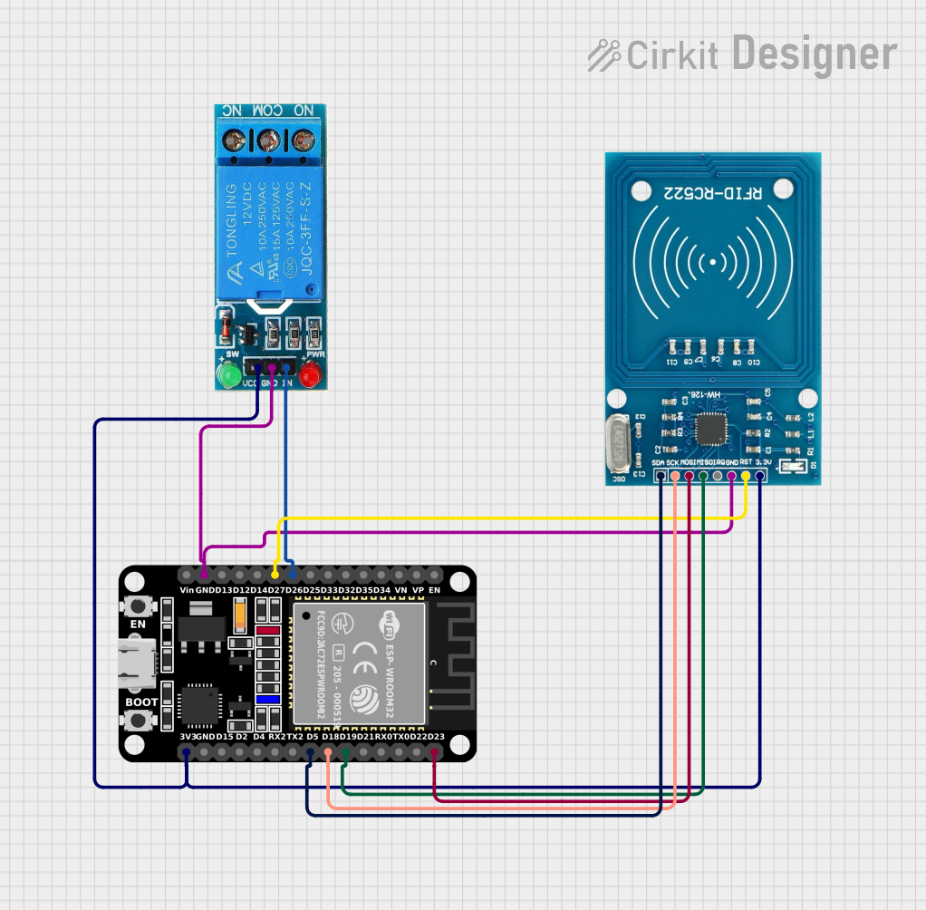
Circuit Documentation
Summary of the Circuit
This circuit integrates an ESP32 microcontroller with an RFID-RC522 reader and a 12V single-channel relay. The ESP32 is responsible for controlling the RFID reader to scan for RFID tags and, upon successful detection of a valid tag, activating the relay. The relay can be used to control a higher power device, such as turning on a light or triggering a motor. The circuit is powered by the ESP32, which also communicates with the RFID reader via SPI protocol.
Component List
ESP32 (30 pin)
- Description: A microcontroller with WiFi and Bluetooth capabilities, featuring a wide range of GPIO pins.
- Purpose: Acts as the central processing unit of the circuit, reads RFID tags, and controls the relay.
RFID-RC522
- Description: An RFID reader/writer module that operates at 13.56 MHz.
- Purpose: To read RFID tags and communicate the tag information to the ESP32.
12V SINGLE CHANNEL RELAY
- Description: An electromechanical switch that allows the ESP32 to control high power devices.
- Purpose: To switch on/off devices in response to RFID tag detection.
Wiring Details
ESP32 (30 pin)
- D26: Connected to the relay module's IN pin to control the relay.
- D27: Connected to the RFID-RC522's RST pin.
- GND: Common ground with RFID-RC522 and the relay module.
- D23: Connected to the RFID-RC522's MOSI pin.
- D19: Connected to the RFID-RC522's MISO pin.
- D18: Connected to the RFID-RC522's SCK pin.
- D5: Connected to the RFID-RC522's SDA pin.
- 3V3: Powers the RFID-RC522 and the relay module.
RFID-RC522
- RST: Connected to the ESP32's D27 pin.
- GND: Common ground with ESP32 and the relay module.
- MOSI: Connected to the ESP32's D23 pin.
- MISO: Connected to the ESP32's D19 pin.
- SCK: Connected to the ESP32's D18 pin.
- SDA: Connected to the ESP32's D5 pin.
- VCC (3.3V): Powered by the ESP32's 3V3 pin.
12V SINGLE CHANNEL RELAY
- IN: Controlled by the ESP32's D26 pin.
- GND: Common ground with ESP32 and the RFID-RC522.
- VCC: Powered by the ESP32's 3V3 pin.
Documented Code
/*
 * ESP32 with Relay and RFID-RC522
 * This code initializes the RFID-RC522 module and reads RFID tags.
 * When a valid RFID tag is detected, it activates a relay connected to the ESP32.
 */

#include <SPI.h>
#include <MFRC522.h>

#define RST_PIN 27 // ESP32 pin connected to RFID RST
#define SS_PIN 5   // ESP32 pin connected to RFID SDA
#define RELAY_PIN 26 // ESP32 pin connected to Relay IN

MFRC522 rfid(SS_PIN, RST_PIN); // Create MFRC522 instance

void setup() {
  Serial.begin(115200);
  SPI.begin(); // Init SPI bus
  rfid.PCD_Init(); // Init MFRC522
  pinMode(RELAY_PIN, OUTPUT);
  digitalWrite(RELAY_PIN, LOW); // Ensure relay is off
  Serial.println("RFID Reader and Relay Initialized");
}

void loop() {
  // Look for new cards
  if (!rfid.PICC_IsNewCardPresent() || !rfid.PICC_ReadCardSerial()) {
    delay(50);
    return;
  }

  Serial.print("Card UID:");
  for (byte i = 0; i < rfid.uid.size; i++) {
    Serial.print(rfid.uid.uidByte[i] < 0x10 ? " 0" : " ");
    Serial.print(rfid.uid.uidByte[i], HEX);
  }
  Serial.println();

  // Activate relay for 5 seconds
  digitalWrite(RELAY_PIN, HIGH);
  delay(5000);
  digitalWrite(RELAY_PIN, LOW);

  // Halt PICC
  rfid.PICC_HaltA();
  // Stop encryption on PCD
  rfid.PCD_StopCrypto1();
}
This code is designed to be uploaded to the ESP32 microcontroller. It initializes the RFID-RC522 module and sets up the relay pin as an output. In the main loop, it continuously checks for new RFID cards. When a card is detected, it prints the card's UID to the serial monitor and activates the relay for 5 seconds.