
Circuit Documentation
Summary of the Circuit
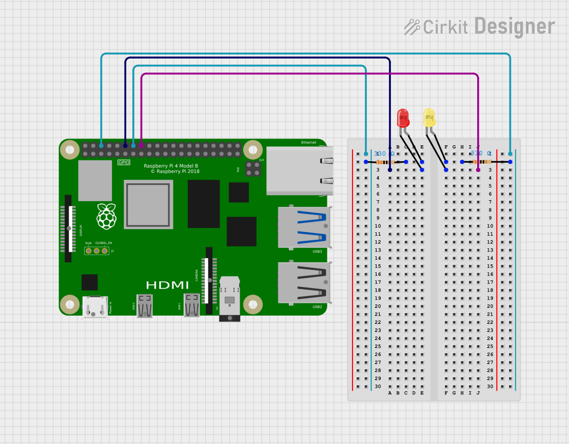
This circuit consists of a Raspberry Pi 4B microcontroller that controls two LEDs: one red and one yellow. Each LED is connected to a GPIO pin on the Raspberry Pi and is in series with a resistor to limit the current. The ground (GND) pins of the Raspberry Pi are connected to the other end of the resistors, completing the circuit for each LED.
Component List
LED: Two Pin (red)
- Description: A red LED that emits red light when powered.
- Pins: cathode, anode
- Purpose: To act as a visual indicator when GPIO18 is driven high.
LED: Two Pin (yellow)
- Description: A yellow LED that emits yellow light when powered.
- Pins: cathode, anode
- Purpose: To act as a visual indicator when GPIO23 is driven high.
Resistor (330 Ohms)
- Description: A resistor with a resistance of 330 Ohms.
- Pins: pin1, pin2
- Purpose: To limit the current flowing through the LEDs, protecting them from damage.
Raspberry Pi 4B
- Description: A microcontroller board capable of performing various computing tasks.
- Pins: 3V3, 5V, multiple GPIOs, GND, and others.
- Purpose: To control the LEDs and execute the embedded code.
Wiring Details
LED: Two Pin (red)
- Cathode: Connected to GPIO18 on the Raspberry Pi.
- Anode: Connected to one end of a 330 Ohm resistor.
LED: Two Pin (yellow)
- Cathode: Connected to GPIO23 on the Raspberry Pi.
- Anode: Connected to one end of a 330 Ohm resistor.
Resistor (330 Ohms)
- One end (pin1 or pin2): Connected to the anode of the corresponding LED.
- The other end (pin1 or pin2): Connected to the GND pin on the Raspberry Pi.
Raspberry Pi 4B
- GPIO18: Connected to the cathode of the red LED.
- GPIO23: Connected to the cathode of the yellow LED.
- GND: Connected to one end of each 330 Ohm resistor.
Documented Code
The code provided is for the Raspberry Pi 4B microcontroller. It is written in C++ for use with the Arduino IDE or compatible systems.
File: sketch.ino
void setup() {
  // put your setup code here, to run once:

}

void loop() {
  // put your main code here, to run repeatedly:

}
This code template includes two main functions: setup() and loop(). The setup() function is intended to contain initialization code that runs once when the system starts. The loop() function is designed to contain the main logic of the program, which will run repeatedly in an infinite loop.
Currently, the code does not contain any specific instructions to control the LEDs. To control the LEDs, you would need to configure the GPIO pins as outputs and then write digital values to them to turn the LEDs on or off.
File: documentation.txt
The file documentation.txt is mentioned in the code list but does not contain any actual code or text. It is likely intended to be a placeholder for additional documentation or notes related to the codebase.