
ESP32-Based Input Control Interface with Joystick, Touch, and Reed Switches
View and Edit Project In Cirkit Designer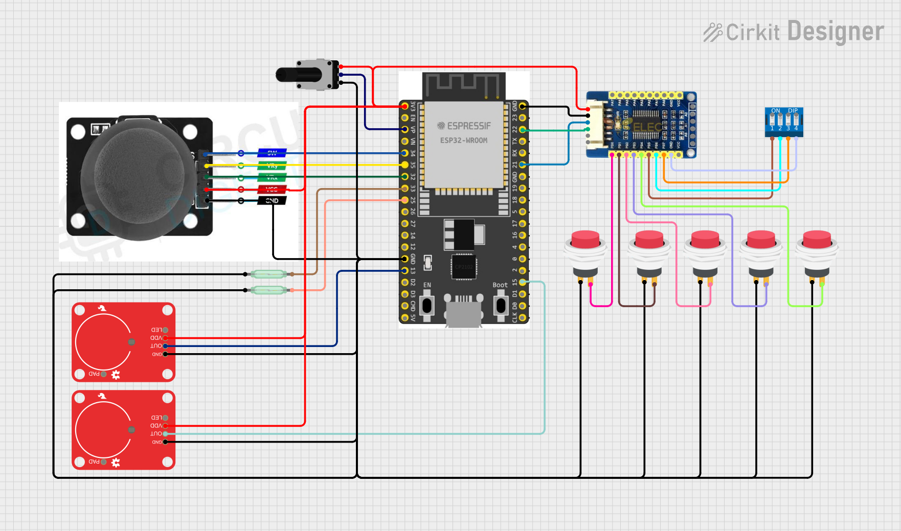
Circuit Documentation
Summary
This circuit integrates various components with an ESP32 Wroom Dev Kit microcontroller to create a multifunctional system. The system includes input devices such as a rotary potentiometer, a joystick module, capacitive touch breakouts, reed switches, push switches, and a DIP switch. The MCP23017 IO Expansion board is used to extend the number of GPIOs available for the ESP32. The circuit is designed to capture various forms of user input and react accordingly.
Component List
- ESP32 Wroom Dev Kit: A microcontroller development board with WiFi and Bluetooth capabilities, featuring a wide range of GPIOs for interfacing with various sensors and peripherals.
- Rotary Potentiometer: A variable resistor with a knob that can be turned to provide analog input based on the rotation angle.
- MCP23017 IO Expansion Board: An I2C-compatible board that provides an additional 16 GPIOs for use with microcontrollers.
- Capacitive Touch Breakout: A sensor module that detects touch or proximity events.
- Reed Switch: A magnetic field-activated switch that closes its contacts in the presence of a magnetic field.
- Joystick Module: An input device that provides two analog axes and a pushbutton switch.
- 2Pin Push Switch: A momentary pushbutton switch that connects or disconnects a circuit when pressed.
- DIP Switch 4 Position: A manual electric switch packaged in a standard dual in-line package with four individual switches.
Wiring Details
ESP32 Wroom Dev Kit
3V3connected to:- Joystick module VCC
- Capacitive Touch Breakout VDD (x2)
- Rotary Potentiometer leg2
- MCP23017 IO Expansion Board VCC
VPconnected to Rotary Potentiometer wiperGPIO 34connected to Joystick module SWGPIO 35connected to Joystick module VRYGPIO 32connected to Joystick module VRXGPIO 33connected to Reed Switch pin 2GPIO 25connected to Reed Switch pin 2GNDconnected to:- Joystick module GND
- Capacitive Touch Breakout GND (x2)
- Rotary Potentiometer leg1
- Reed Switch pin 1 (x2)
- 2Pin Push Switch Input + (x4)
- MCP23017 IO Expansion Board GND
GPIO 13connected to Capacitive Touch Breakout OUTGPIO 22connected to MCP23017 IO Expansion Board SCLGPIO 21connected to MCP23017 IO Expansion Board SDAGPIO 15connected to Capacitive Touch Breakout OUT
Rotary Potentiometer
leg1connected to GNDwiperconnected to ESP32 VPleg2connected to 3V3
MCP23017 IO Expansion Board
VCCconnected to 3V3GNDconnected to GNDSDAconnected to ESP32 GPIO 21SCLconnected to ESP32 GPIO 22PB0connected to 2Pin Push Switch Output +PB1connected to 2Pin Push Switch Output +PB2connected to 2Pin Push Switch Output +PB3connected to 2Pin Push Switch Output +PB4connected to 2Pin Push Switch Output +PB5connected to DIP Switch 4 Position 1PB6connected to DIP Switch 4 Position 2PB7connected to DIP Switch 4 Position 3PA0-PA7(Not connected)
Capacitive Touch Breakout
GNDconnected to GNDVDDconnected to 3V3OUTconnected to ESP32 GPIO 13 and GPIO 15
Reed Switch
pin 1connected to GNDpin 2connected to ESP32 GPIO 33 and GPIO 25
Joystick Module
GNDconnected to GNDVCCconnected to 3V3SWconnected to ESP32 GPIO 34VRYconnected to ESP32 GPIO 35VRXconnected to ESP32 GPIO 32
2Pin Push Switch
Input +connected to GNDOutput +connected to MCP23017 IO Expansion Board PB0, PB1, PB2, PB3, PB4
DIP Switch 4 Position
1connected to MCP23017 IO Expansion Board PB52connected to MCP23017 IO Expansion Board PB63connected to MCP23017 IO Expansion Board PB74(Not connected)
Documented Code
sketch.ino
void setup() {
  // put your setup code here, to run once:

}

void loop() {
  // put your main code here, to run repeatedly:

}
documentation.txt
(No code provided for this file)