Cirkit Designer
Your all-in-one circuit design IDE
Home /
Project Documentation
Arduino-Based Heart Rate Monitor with LED and Buzzer Alerts
Circuit Documentation
Summary
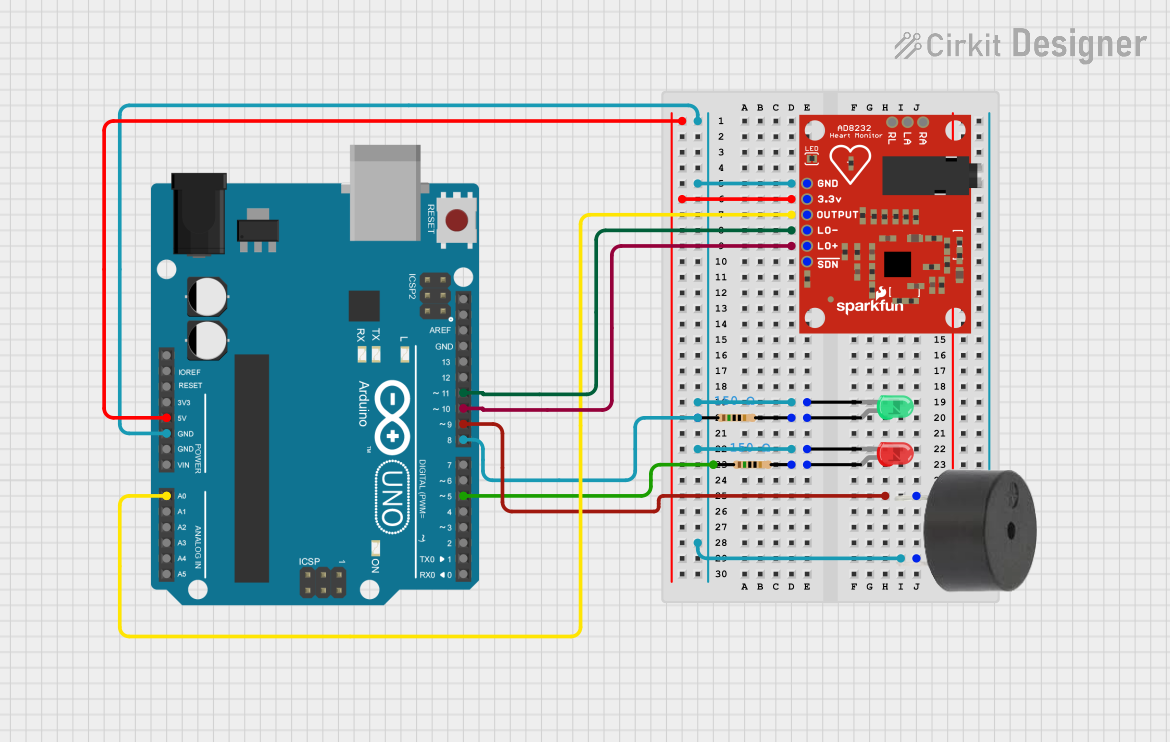
This circuit is designed to monitor heart rate using an AD8232 Heart Rate Monitor and an Arduino UNO. The circuit includes visual and auditory indicators using LEDs and a buzzer. The Arduino UNO processes the heart rate signal and provides feedback through the LEDs and buzzer based on the status of the heart rate monitor.
Component List
Arduino UNO
- Description: A microcontroller board based on the ATmega328P.
- Pins: UNUSED, IOREF, Reset, 3.3V, 5V, GND, Vin, A0, A1, A2, A3, A4, A5, SCL, SDA, AREF, D13, D12, D11, D10, D9, D8, D7, D6, D5, D4, D3, D2, D1, D0
LED: Two Pin (red)
- Description: A red LED with two pins: cathode and anode.
- Pins: cathode, anode
LED: Two Pin (green)
- Description: A green LED with two pins: cathode and anode.
- Pins: cathode, anode
AD8232 HeartRate Monitor
- Description: A heart rate monitor sensor.
- Pins: GND, 3.3v, OUTPUT, LO-, LO+, SDN, RA, LA, RL
Buzzer
- Description: A simple buzzer with two pins: PIN and GND.
- Pins: PIN, GND
Resistor (150 Ohms)
- Description: A resistor with a resistance of 150 Ohms.
- Pins: pin1, pin2
Resistor (150 Ohms)
- Description: A resistor with a resistance of 150 Ohms.
- Pins: pin1, pin2
Wiring Details
Arduino UNO
- GND is connected to:
- AD8232 HeartRate Monitor (GND)
- Resistor (pin1)
- LED: Two Pin (green) (cathode)
- LED: Two Pin (red) (cathode)
- Buzzer (GND)
- Arduino UNO (D8)
- 5V is connected to AD8232 HeartRate Monitor (3.3v)
- A0 is connected to AD8232 HeartRate Monitor (OUTPUT)
- D11 is connected to AD8232 HeartRate Monitor (LO-)
- D10 is connected to AD8232 HeartRate Monitor (LO+)
- D9 is connected to Buzzer (PIN)
- D5 is connected to Resistor (pin1)
LED: Two Pin (red)
- cathode is connected to Arduino UNO (GND)
- anode is connected to Resistor (pin2)
LED: Two Pin (green)
- cathode is connected to Arduino UNO (GND)
- anode is connected to Resistor (pin2)
AD8232 HeartRate Monitor
- GND is connected to Arduino UNO (GND)
- 3.3v is connected to Arduino UNO (5V)
- OUTPUT is connected to Arduino UNO (A0)
- LO- is connected to Arduino UNO (D11)
- LO+ is connected to Arduino UNO (D10)
Buzzer
- PIN is connected to Arduino UNO (D9)
- GND is connected to Arduino UNO (GND)
Resistor (150 Ohms)
- pin1 is connected to Arduino UNO (D5)
- pin2 is connected to LED: Two Pin (red) (anode)
Resistor (150 Ohms)
- pin1 is connected to Arduino UNO (GND)
- pin2 is connected to LED: Two Pin (green) (anode)
Code Documentation
// Pin definitions
const int redLEDPin = 5;       // Red LED connected to D5
const int greenLEDPin = 8;     // Green LED connected to D8
const int buzzerPin = 9;       // Buzzer connected to D9
const int ad8232OutputPin = A0; // AD8232 OUTPUT connected to A0
const int loPlusPin = 10;      // AD8232 LO+ connected to D10
const int loMinusPin = 11;     // AD8232 LO- connected to D11

void setup() {
  // Initialize serial communication
  Serial.begin(9600);

  // Initialize pin modes
  pinMode(redLEDPin, OUTPUT);
  pinMode(greenLEDPin, OUTPUT);
  pinMode(buzzerPin, OUTPUT);
  pinMode(ad8232OutputPin, INPUT);
  pinMode(loPlusPin, INPUT);
  pinMode(loMinusPin, INPUT);

  // Turn off LEDs and buzzer initially
  digitalWrite(redLEDPin, LOW);
  digitalWrite(greenLEDPin, LOW);
  digitalWrite(buzzerPin, LOW);
}

void loop() {
  // Read the AD8232 output
  int heartRateSignal = analogRead(ad8232OutputPin);

  // Read the LO+ and LO- pins
  int loPlusStatus = digitalRead(loPlusPin);
  int loMinusStatus = digitalRead(loMinusPin);

  // Print heart rate signal to Serial Monitor
  Serial.print("Heart Rate Signal: ");
  Serial.println(heartRateSignal);

  // Check if leads are off
  if (loPlusStatus == 1 || loMinusStatus == 1) {
    Serial.println("Leads off detected!");
    digitalWrite(redLEDPin, HIGH);  // Turn on red LED
    digitalWrite(greenLEDPin, LOW); // Turn off green LED
    digitalWrite(buzzerPin, HIGH);  // Turn on buzzer
  } else {
    digitalWrite(redLEDPin, LOW);   // Turn off red LED
    digitalWrite(greenLEDPin, HIGH);// Turn on green LED
    digitalWrite(buzzerPin, LOW);   // Turn off buzzer
  }

  // Add a small delay to avoid flooding the Serial Monitor
  delay(100);
}
This code initializes the pins, reads the heart rate signal, and provides feedback through the LEDs and buzzer based on the status of the heart rate monitor. The red LED and buzzer are activated if the leads are off, while the green LED is activated if the leads are properly connected.