
Circuit Documentation
Summary
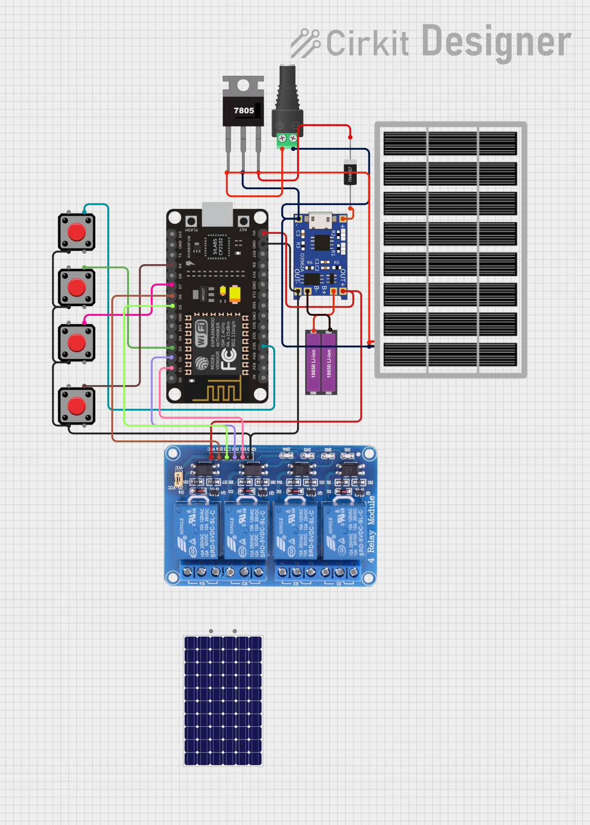
This circuit is designed to interface an ESP8266 NodeMCU microcontroller with a 4-channel relay module, allowing for the control of external devices. The circuit includes a charging module for a pair of 18650 Li-ion batteries, which are used as the power source. A solar panel is incorporated to provide a charging capability through the TP4056 charging module. The circuit also includes a voltage regulator (7805) to ensure stable voltage supply, rectifier diode (1N4007) for polarity protection, and multiple pushbuttons for user input. The ESP8266 NodeMCU controls the relay module and reads the state of the pushbuttons.
Component List
TP4056
- Description: Lithium Battery Charger Module
- Pins: OUT-, B-, B+, OUT+, IN-, IN+
18650 Li-ion Battery x 2
- Description: Rechargeable Battery Pack
- Pins: +, -
1N4007 Rectifier Diode
- Description: General Purpose Rectifier Diode
- Pins: Cathode, Anode
Solar Panel
- Description: Photovoltaic Panel for Charging
- Pins: gnd, vcc
Relay 4 Channel 5v
- Description: 4-Channel Relay Module for Switching High Power Devices
- Pins: GND, IN1, IN2, IN3, IN4, VCC, COM1, COM2, COM3, COM4, NO1, NO2, NO3, NO4, NC1, NC2, NC3, NC4
Pushbutton
- Description: Momentary Pushbutton Switch
- Pins: Pin 2, Pin 1, Pin 3, Pin 4
2.1mm Barrel Jack with Terminal Block
- Description: Power Connector for External Power Supply
- Pins: POS, NEG
7805
- Description: Voltage Regulator
- Pins: Vin, Gnd, Vout
ESP8266 NodeMCU
- Description: WiFi Microcontroller Module
- Pins: D0, D1, D2, D3, D4, 3V3, GND, D5, D6, D7, D8, RX, TX, A0, RSV, SD3, SD2, SD1, CMD, SD0, CLK, EN, RST, VIN
Wiring Details
TP4056
- OUT-: Connected to GND of the circuit
- B-: Connected to the negative terminal of the 18650 Li-ion Battery x 2
- B+: Connected to the positive terminal of the 18650 Li-ion Battery x 2
- OUT+: Connected to VIN of the ESP8266 NodeMCU and VCC of the Relay 4 Channel 5v
- IN-: Connected to GND of the circuit (shared with 7805 Gnd, Barrel Jack NEG, and Solar Panel gnd)
- IN+: Connected to the Anode of the 1N4007 Rectifier Diode
18650 Li-ion Battery x 2
- +: Connected to B+ of TP4056
- -: Connected to B- of TP4056
1N4007 Rectifier Diode
- Cathode: Connected to Vout of the 7805 Voltage Regulator
- Anode: Connected to IN+ of TP4056
Solar Panel
- gnd: Connected to GND of the circuit (shared with 7805 Gnd, Barrel Jack NEG, and TP4056 IN-)
- vcc: Connected to Vin of the 7805 Voltage Regulator
Relay 4 Channel 5v
- GND: Connected to GND of the circuit
- IN1: Connected to D1 of the ESP8266 NodeMCU
- IN2: Connected to D2 of the ESP8266 NodeMCU
- IN3: Connected to D5 of the ESP8266 NodeMCU
- IN4: Connected to D6 of the ESP8266 NodeMCU
- VCC: Connected to VIN of the ESP8266 NodeMCU and OUT+ of TP4056
Pushbutton (Multiple Instances)
- Pin 4: Connected to various GPIO pins on the ESP8266 NodeMCU (D3, D7, RX, SD3)
- Pin 2: Connected to GND of the circuit
2.1mm Barrel Jack with Terminal Block
- POS: Connected to Vin of the 7805 Voltage Regulator
- NEG: Connected to GND of the circuit (shared with 7805 Gnd, Solar Panel gnd, and TP4056 IN-)
7805
- Vin: Connected to POS of the Barrel Jack and vcc of the Solar Panel
- Gnd: Connected to GND of the circuit (shared with Barrel Jack NEG, Solar Panel gnd, and TP4056 IN-)
- Vout: Connected to the Cathode of the 1N4007 Rectifier Diode
ESP8266 NodeMCU
- D1, D2, D5, D6: Connected to IN1, IN2, IN3, IN4 of the Relay 4 Channel 5v respectively
- D3, D7, RX, SD3: Connected to Pin 4 of different Pushbutton instances
- GND: Connected to GND of the circuit (shared with multiple components)
- VIN: Connected to OUT+ of TP4056 and VCC of the Relay 4 Channel 5v
Documented Code
No code was provided for the ESP8266 NodeMCU or any other microcontroller in the circuit. Therefore, this section is left blank until the relevant code is supplied.