
Arduino-Powered Traffic Light Control System with RFID and Ultrasonic Sensors
View and Edit Project In Cirkit Designer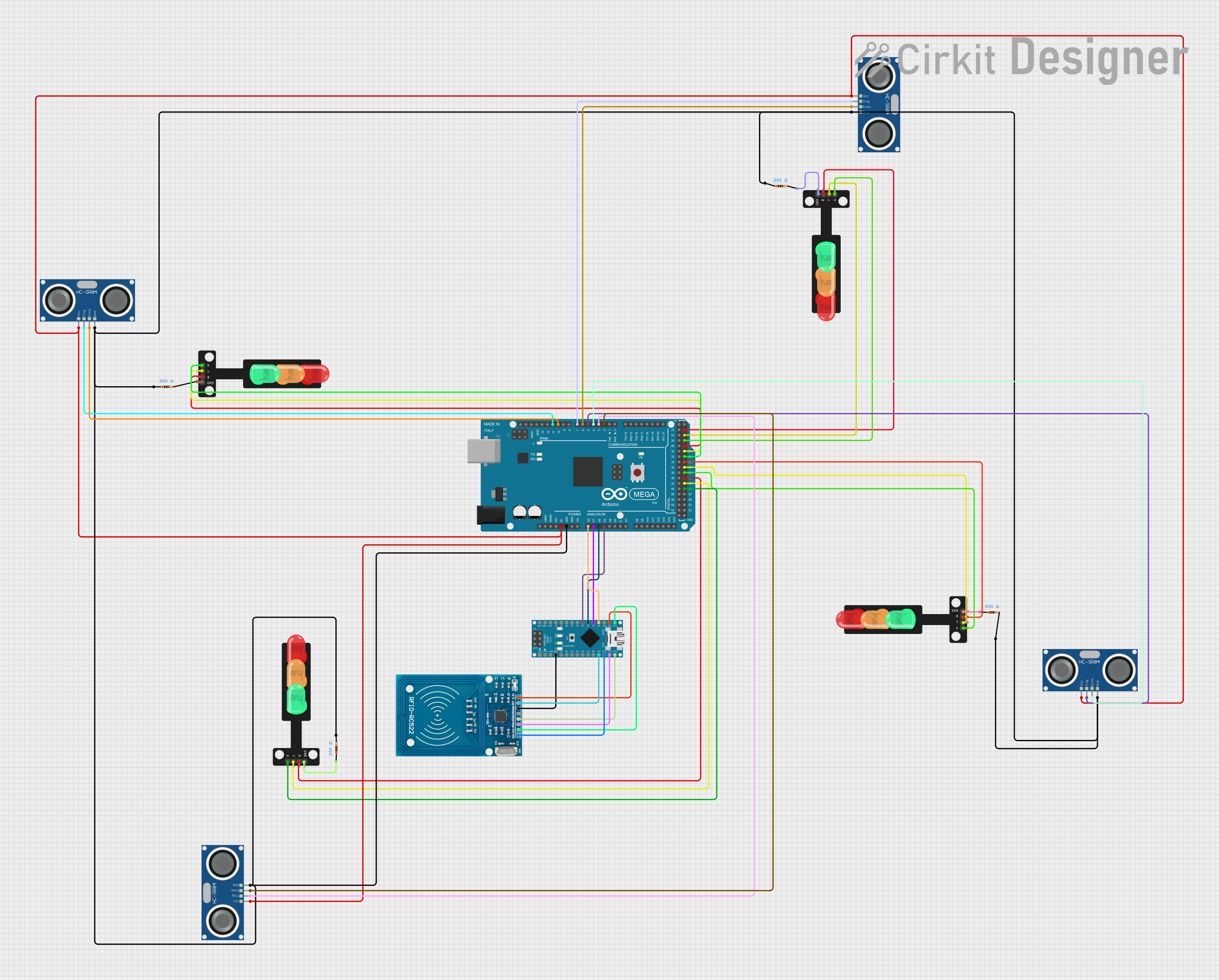
Circuit Documentation
Summary
The circuit in question is designed to interface an Arduino Nano with an RFID-RC522 module and to connect an Arduino Mega 2560 with multiple HC-SR04 Ultrasonic Sensors and Traffic Lights. The Arduino Nano is used to control the RFID-RC522 module, while the Arduino Mega 2560 manages the ultrasonic sensors for distance measurement and controls the traffic lights based on the sensor inputs. The circuit includes resistors for current limiting purposes with the traffic lights.
Component List
Microcontrollers
- Arduino Nano: A compact board based on the ATmega328 microcontroller, featuring digital and analog I/O pins.
- Arduino Mega 2560: A microcontroller board based on the ATmega2560, with a large number of digital and analog I/O pins, suitable for complex projects.
Sensors
- RFID-RC522: An RFID reader/writer module for contactless communication at 13.56MHz.
- HC-SR04 Ultrasonic Sensor: An ultrasonic ranging module that provides 2cm to 400cm non-contact measurement functionality.
Actuators
- Traffic Light: A module with three LEDs (Red, Yellow, Green) that simulates a traffic light.
Passive Components
- Resistor: A passive two-terminal electrical component that implements electrical resistance as a circuit element.
Wiring Details
Arduino Nano
- GND connected to RFID-RC522 GND.
- D9 connected to RFID-RC522 RST.
- D10 connected to RFID-RC522 SDA.
- D11/MOSI connected to RFID-RC522 MOSI.
- D12/MISO connected to RFID-RC522 MISO.
- 3V3 connected to RFID-RC522 VCC (3.3V).
- D13/SCK connected to RFID-RC522 SCK.
- A0 - A3 connected to corresponding pins A0 - A3 on Arduino Mega 2560.
Arduino Mega 2560
- 5V connected to VCC of all HC-SR04 Ultrasonic Sensors.
- GND connected to GND of all HC-SR04 Ultrasonic Sensors and one terminal of each resistor.
- D2 PWM - D11 PWM connected to TRIG and ECHO pins of HC-SR04 Ultrasonic Sensors.
- D23, D25, D27, D29, D31, D33, D35, D37, D39, D41, D43, D45 connected to Traffic Light modules' Red, Yellow, and Green pins.
- A0 - A3 connected to corresponding pins A0 - A3 on Arduino Nano.
RFID-RC522
- Wired to Arduino Nano as specified above.
HC-SR04 Ultrasonic Sensors
- VCC connected to 5V on Arduino Mega 2560.
- GND connected to GND on Arduino Mega 2560.
- TRIG and ECHO pins connected to specified PWM pins on Arduino Mega 2560.
Traffic Lights
- Green, Yellow, Red pins connected to specified pins on Arduino Mega 2560.
- GND connected to the other terminal of the resistors whose one terminal is connected to GND on Arduino Mega 2560.
Resistors
- One terminal connected to GND on Arduino Mega 2560.
- Other terminal connected to GND on Traffic Light modules.
Documented Code
Arduino Nano Code
void setup() {
  // put your setup code here, to run once:

}

void loop() {
  // put your main code here, to run repeatedly:

}
Arduino Mega 2560 Code
#include<TimerOne.h>

// ... (initialization and pin assignments)

void setup(){
  // Setup code including pin mode settings and serial communication
}

void loop()
{
  // Main loop code including reading button states and ultrasonic sensor values
}

// Interrupt function to read ultrasonic sensor values
void softInterr()
{
  // Reading from ultrasonic sensors and storing the distance
}

// Functions to control the traffic light signals
void signal1Function()
{
  // Control logic for signal 1
}

void signal2Function()
{
  // Control logic for signal 2
}

void signal3Function()
{
  // Control logic for signal 3
}

void signal4Function()
{
  // Control logic for signal 4
}

// Functions to handle the case when there are no vehicles
void signal01Function()
{
  // Control logic for no vehicles at signal 1
}

void signal02Function()
{
  // Control logic for no vehicles at signal 2
}

void signal03Function()
{
  // Control logic for no vehicles at signal 3
}

void signal04Function()
{
  // Control logic for no vehicles at signal 4
}

// Function to set all LEDs to a low state except red ones
void low()
{
  // Set all LEDs to low except red ones
}
This code snippet is a simplified representation of the actual code used in the Arduino Mega 2560. It includes the setup of pins, the main loop with logic for reading sensor values and controlling traffic lights, interrupt service routines for ultrasonic sensors, and additional functions for traffic light control.