
ESP32-Based Smart Garbage Monitoring System with Ultrasonic Sensor and Traffic Light Indicators
View and Edit Project In Cirkit Designer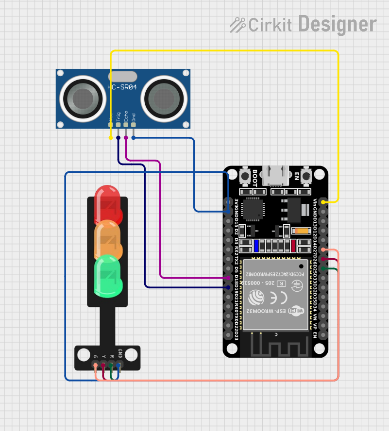
Circuit Documentation
Summary
This document provides a detailed overview of a smart garbage maintaining system. The system uses an ESP32 microcontroller to control a traffic light module and an HC-SR04 ultrasonic sensor. The ESP32 is programmed to monitor the fill level of a garbage bin using the ultrasonic sensor and display the status on an LCD. The traffic light module indicates the fill level, and a buzzer alerts when the bin is almost full. The system also connects to the Blynk platform for remote monitoring.
Component List
ESP32 (30 pin)
- Description: A powerful microcontroller with Wi-Fi and Bluetooth capabilities.
- Pins: EN, VP, VN, D34, D35, D32, D33, D25, D26, D27, D14, D12, D13, GND, Vin, D23, D22, TX0, RX0, D21, D19, D18, D5, TX2, RX2, D4, D2, D15, 3V3
HC-SR04 Ultrasonic Sensor
- Description: A sensor used to measure distance by using ultrasonic waves.
- Pins: VCC, TRIG, ECHO, GND
Traffic Light
- Description: A module with three LEDs (Red, Yellow, Green) used to indicate different statuses.
- Pins: Green, Yellow, Red, GND
Wiring Details
ESP32 (30 pin)
- D25: Connected to Red pin of Traffic Light
- D26: Connected to Yellow pin of Traffic Light
- D27: Connected to Green pin of Traffic Light
- Vin: Connected to VCC pin of HC-SR04 Ultrasonic Sensor
- D19: Connected to TRIG pin of HC-SR04 Ultrasonic Sensor
- D18: Connected to ECHO pin of HC-SR04 Ultrasonic Sensor
- GND: Connected to GND pin of Traffic Light and HC-SR04 Ultrasonic Sensor
HC-SR04 Ultrasonic Sensor
- VCC: Connected to Vin pin of ESP32
- TRIG: Connected to D19 pin of ESP32
- ECHO: Connected to D18 pin of ESP32
- GND: Connected to GND pin of ESP32 and Traffic Light
Traffic Light
- Red: Connected to D25 pin of ESP32
- Yellow: Connected to D26 pin of ESP32
- Green: Connected to D27 pin of ESP32
- GND: Connected to GND pin of ESP32 and HC-SR04 Ultrasonic Sensor
Code Documentation
#define BLYNK_TEMPLATE_ID "TMPL3_mZ5JXni"
#define BLYNK_TEMPLATE_NAME "Smart Garbage Maintaining System"
#define BLYNK_AUTH_TOKEN "yrA62Lf3TT-rvYpnep6P5okcO-021lWy"
#define PIN_RED    25 // The ESP32 pin GPIO25 connected to R pin of traffic light module
#define PIN_YELLOW 26 // The ESP32 pin GPIO26 connected to Y pin of traffic light module
#define PIN_GREEN  27

#define RED_TIME     500 // RED time in millisecond
#define YELLOW_TIME  500 // YELLOW time in millisecond
#define GREEN_TIME   500 // GREEN time in millisecond

#include <LiquidCrystal_I2C.h>
#include <Wire.h>
#include <WiFi.h>
#include <WiFiClient.h>
#include <BlynkSimpleEsp32.h>
#include <NewPing.h>
#define TRIGGER_PIN  19  // Arduino pin tied to trigger pin on the ultrasonic sensor.
#define ECHO_PIN     18  // Arduino pin tied to echo pin on the ultrasonic sensor.
#define MAX_DISTANCE 200 // Maximum distance we want to ping for (in centimeters). Maximum sensor distance is rated at 400-500cm.
BlynkTimer timer; // Creating a timer object

char ssid[] = "Training Hall_EXT";
char pass[] = "IRDT#1982";

LiquidCrystal_I2C lcd(0x27, 20, 4);  // set the LCD address to 0x27 for a 16 chars and 2 line display
NewPing sonar(TRIGGER_PIN, ECHO_PIN, MAX_DISTANCE); // NewPing setup of pins and maximum distance.

const int buzzerPin = 23;
int bucketFilledUpto = 0;

void setup() {
  Serial.begin(115200); // Starts the serial communication

  lcd.init();
  lcd.backlight();
  show(0);
  pinMode(buzzerPin, OUTPUT);
  digitalWrite(buzzerPin, HIGH);
  timer.setInterval(1000L, myTimerEvent); //Staring a timer
  Blynk.begin(BLYNK_AUTH_TOKEN,ssid,pass);
  pinMode(PIN_RED, OUTPUT);
  pinMode(PIN_YELLOW, OUTPUT);
  pinMode(PIN_GREEN, OUTPUT);
}

void myTimerEvent() // This loop defines what happens when timer is triggered
{
  Blynk.virtualWrite(V0,bucketFilledUpto);
}

void loop() {
  delay(50);                     // Wait 50ms between pings (about 20 pings/sec). 29ms should be the shortest delay between pings.
  float distanceCm=sonar.ping_cm();

  Serial.print(bucketFilledUpto);
  Serial.print("Ping: ");
  Serial.print(distanceCm); // Send ping, get distance in cm and print result (0 = outside set distance range)
  Serial.println("cm");
  digitalWrite(PIN_RED, LOW);    // turn off
  digitalWrite(PIN_YELLOW, LOW); // turn off
  // digitalWrite(PIN_GREEN, HIGH); // turn on
  // delay(GREEN_TIME);
  bucketFilledUpto = ((18-distanceCm)*100)/18;
  show(bucketFilledUpto);
  if(distanceCm <= 5){
    digitalWrite(buzzerPin, LOW);
    digitalWrite(PIN_RED, HIGH);    // turn off
    digitalWrite(PIN_YELLOW, LOW); // turn off
    digitalWrite(PIN_GREEN, LOW); // turn on
    delay(500);
  } else {
    digitalWrite(buzzerPin, HIGH);
    digitalWrite(PIN_RED, LOW);    // turn off
    digitalWrite(PIN_YELLOW, LOW); // turn off
    digitalWrite(PIN_GREEN, HIGH); // turn on
    delay(500);
  }

  Blynk.run();
  timer.run();
}

void show(float d){
  lcd.setCursor(0,0);
  lcd.print("Name : Anand,Anshu");
  lcd.setCursor(0,1);
  lcd.print("Member: 3");
  lcd.setCursor(0,2);
  lcd.print("Project Name: GMS");
  lcd.setCursor(0,3);
  lcd.print("Status :");
  lcd.setCursor(10, 3);
  lcd.print(d);
  lcd.print("%");
}
This code initializes the ESP32, sets up the ultrasonic sensor, traffic light module, and LCD display. It continuously monitors the distance to the garbage level, updates the LCD display, and controls the traffic light and buzzer based on the fill level. The system also sends data to the Blynk platform for remote monitoring.