
ESP32 and Arduino UNO Smart Relay Control with I2C LCD Display
View and Edit Project In Cirkit Designer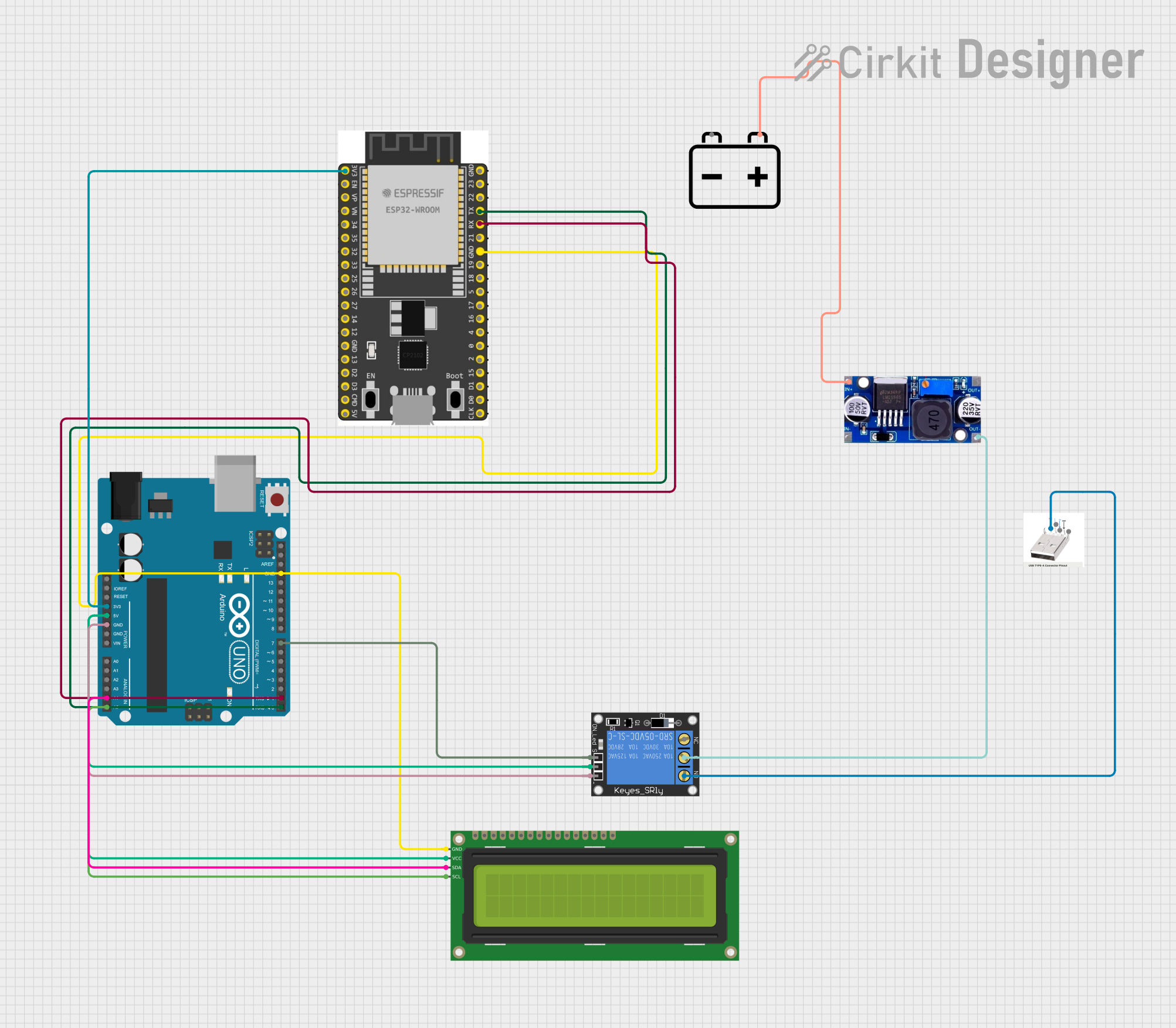
Circuit Documentation
Summary
This document provides a detailed overview of a circuit that includes various components such as an Arduino UNO, ESP32 Wroom Dev Kit, 1-Channel Relay, 16x2 I2C LCD, USB Port, 12V Battery, and LM2596 voltage regulator. The circuit is designed to interface these components for a specific application, with microcontrollers programmed to control the operation.
Component List
1-Channel Relay (5V 10A)
- Description: A relay module that allows a low-power microcontroller to control a high-power device.
- Pins: NC, signal, C, power, NO, ground
16x2 I2C LCD
- Description: A 16x2 character LCD display with I2C interface.
- Pins: GND, VCC, SDA, SCL
USB Port type A
- Description: A standard USB port for data and power connections.
- Pins: D-, D+, GND
ESP32 Wroom Dev Kit
- Description: A development board for the ESP32 microcontroller, featuring Wi-Fi and Bluetooth capabilities.
- Pins: 3V3, EN, VP, VN, GPIO 34, GPIO 35, GPIO 32, GPIO 33, GPIO 25, GPIO 26, GPIO 27, GPIO 14, GND, GPIO 13, SD2, SD3, CMD, V5, GPIO 23, GPIO 22, TXD, RXD, GPIO 21, GPIO 19, GPIO 18, GPIO 5, GPIO 17, GPIO 16, GPIO 4, GPIO 0, GPIO 2, GPIO 15, SD1, SD0, CLK
12V Battery
- Description: A 12V battery used as a power source.
- Pins: -, +
LM2596
- Description: A voltage regulator module that steps down voltage from a higher level to a lower level.
- Pins: IN, OUT
Arduino UNO
- Description: A popular microcontroller board based on the ATmega328P.
- Pins: UNUSED, IOREF, Reset, 3.3V, 5V, GND, Vin, A0, A1, A2, A3, A4, A5, SCL, SDA, AREF, D13, D12, D11, D10, D9, D8, D7, D6, D5, D4, D3, D2, D1, D0
Wiring Details
1-Channel Relay (5V 10A)
- power connected to 5V of Arduino UNO
- ground connected to GND of Arduino UNO
- signal connected to D7 of Arduino UNO
- C connected to OUT of LM2596
- NO connected to D- of USB Port type A
16x2 I2C LCD
- GND connected to GND of Arduino UNO and ESP32 Wroom Dev Kit
- VCC connected to 5V of Arduino UNO
- SDA connected to A4 of Arduino UNO
- SCL connected to A5 of Arduino UNO
USB Port type A
- D- connected to NO of 1-Channel Relay (5V 10A)
ESP32 Wroom Dev Kit
- 3V3 connected to 3.3V of Arduino UNO
- TXD connected to D0 of Arduino UNO
- RXD connected to D1 of Arduino UNO
- GND connected to GND of Arduino UNO and 16x2 I2C LCD
12V Battery
- + connected to IN of LM2596
LM2596
- IN connected to + of 12V Battery
- OUT connected to C of 1-Channel Relay (5V 10A)
Arduino UNO
- 3.3V connected to 3V3 of ESP32 Wroom Dev Kit
- D0 connected to TXD of ESP32 Wroom Dev Kit
- D1 connected to RXD of ESP32 Wroom Dev Kit
- GND connected to GND of 16x2 I2C LCD, ESP32 Wroom Dev Kit, and 1-Channel Relay (5V 10A)
- 5V connected to VCC of 16x2 I2C LCD and power of 1-Channel Relay (5V 10A)
- A4 connected to SDA of 16x2 I2C LCD
- A5 connected to SCL of 16x2 I2C LCD
- D7 connected to signal of 1-Channel Relay (5V 10A)
Documented Code
ESP32 Wroom Dev Kit
sketch.ino
void setup() {
  // put your setup code here, to run once:

}

void loop() {
  // put your main code here, to run repeatedly:

}
Arduino UNO
sketch.ino
void setup() {
  // put your setup code here, to run once:

}

void loop() {
  // put your main code here, to run repeatedly:

}
This documentation provides a comprehensive overview of the circuit, including the components used, their connections, and the code for the microcontrollers.