
Arduino Mega 2560 Controlled Robot with Ultrasonic Sensors and Bluetooth Connectivity
View and Edit Project In Cirkit Designer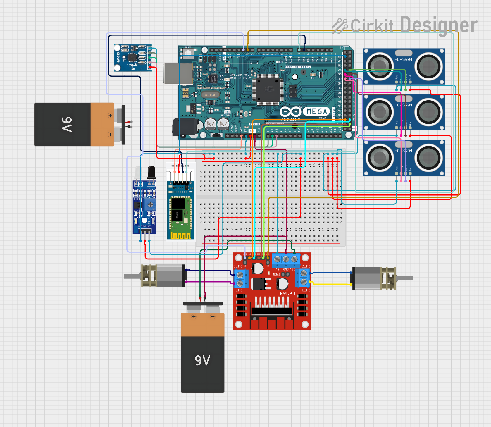
Circuit Documentation
Summary
This circuit is designed around the Arduino Mega 2560 microcontroller and includes a variety of sensors and modules to perform various functions. The circuit features ultrasonic sensors (HC-SR04) for distance measurement, a Bluetooth module (HC-06) for wireless communication, an accelerometer (AITrip ADXL335 GY-61) for motion detection, an IR obstacle sensor (Sensor FC-51 IR), and a motor driver (L298N) to control DC motors. The circuit is powered by a 9V battery and is capable of driving two DC Mini Metal Gear Motors. The Arduino Mega 2560 is the central processing unit that reads sensor data, controls the motors, and communicates with external devices via Bluetooth.
Component List
Arduino Mega 2560
- Microcontroller board based on the ATmega2560
- Provides a large number of IO pins, including digital, analog, and PWM capable pins
- Used as the main controller for the circuit
Battery 9V
- Provides power to the circuit
- Used to supply the motor driver and indirectly powers other components through the Arduino Mega 2560
HC-SR04 Ultrasonic Sensor
- Ultrasonic distance measuring module
- Uses sonar to determine the distance to an object
- Multiple instances are used for multi-directional distance sensing
L298N DC Motor Driver
- Dual H-bridge motor driver
- Capable of driving two DC motors with direction and speed control
DC Mini Metal Gear Motor
- Small DC motor with a gearbox for increased torque
- Two instances are used for driving a vehicle or robotic platform
HC-06 Bluetooth Module
- Wireless serial communication module
- Allows for Bluetooth connectivity with other devices
Sensor FC-51 IR
- Infrared obstacle avoidance sensor
- Detects the presence of an object within a certain range
AITrip ADXL335 GY-61
- Analog 3-axis accelerometer
- Measures acceleration in three dimensions
Wiring Details
Arduino Mega 2560
3V3connected to HC-06 VCC5Vconnected to AITrip ADXL335 GY-61 VCC, L298N 5V, Sensor FC-51 IR VCC, and all HC-SR04 VCC pinsGNDconnected to HC-06 GND, AITrip ADXL335 GY-61 GND, Sensor FC-51 IR GND, and all HC-SR04 GND pinsA0connected to AITrip ADXL335 GY-61 X-OutA1connected to AITrip ADXL335 GY-61 Y-OutA2connected to AITrip ADXL335 GY-61 Z-OutD15/RX3connected to HC-06 TXDD14/TX3connected to HC-06 RXDD9 PWMconnected to L298N ENAD10 PWMconnected to L298N ENBD52connected to L298N IN2D50connected to L298N IN4D32connected to HC-SR04 TRIG (Instance 1)D30connected to HC-SR04 TRIG (Instance 2)D28connected to HC-SR04 TRIG (Instance 3)D22connected to Sensor FC-51 IR OUTD53connected to L298N IN1D51connected to L298N IN3D33connected to HC-SR04 ECHO (Instance 1)D31connected to HC-SR04 ECHO (Instance 2)D29connected to HC-SR04 ECHO (Instance 3)
Battery 9V
VCCconnected to L298N 12VGNDconnected to L298N GND
L298N DC Motor Driver
OUT1connected to DC Mini Metal Gear Motor IN2 (Instance 1)OUT2connected to DC Mini Metal Gear Motor IN1 (Instance 1)OUT3connected to DC Mini Metal Gear Motor IN2 (Instance 2)OUT4connected to DC Mini Metal Gear Motor IN1 (Instance 2)
Documented Code
Arduino Mega 2560 Code (sketch.ino)
void setup() {
  // put your setup code here, to run once:

}

void loop() {
  // put your main code here, to run repeatedly:

}
Additional Notes
- The provided code is a template and does not contain any functional code specific to the circuit's operation.
- The user is expected to write the setup and loop functions to initialize the components and define the circuit's behavior during operation.