Arduino Pro Mini Based CO2 Monitoring System with LoRa Wireless Transmission
Circuit Documentation
Summary of the Circuit
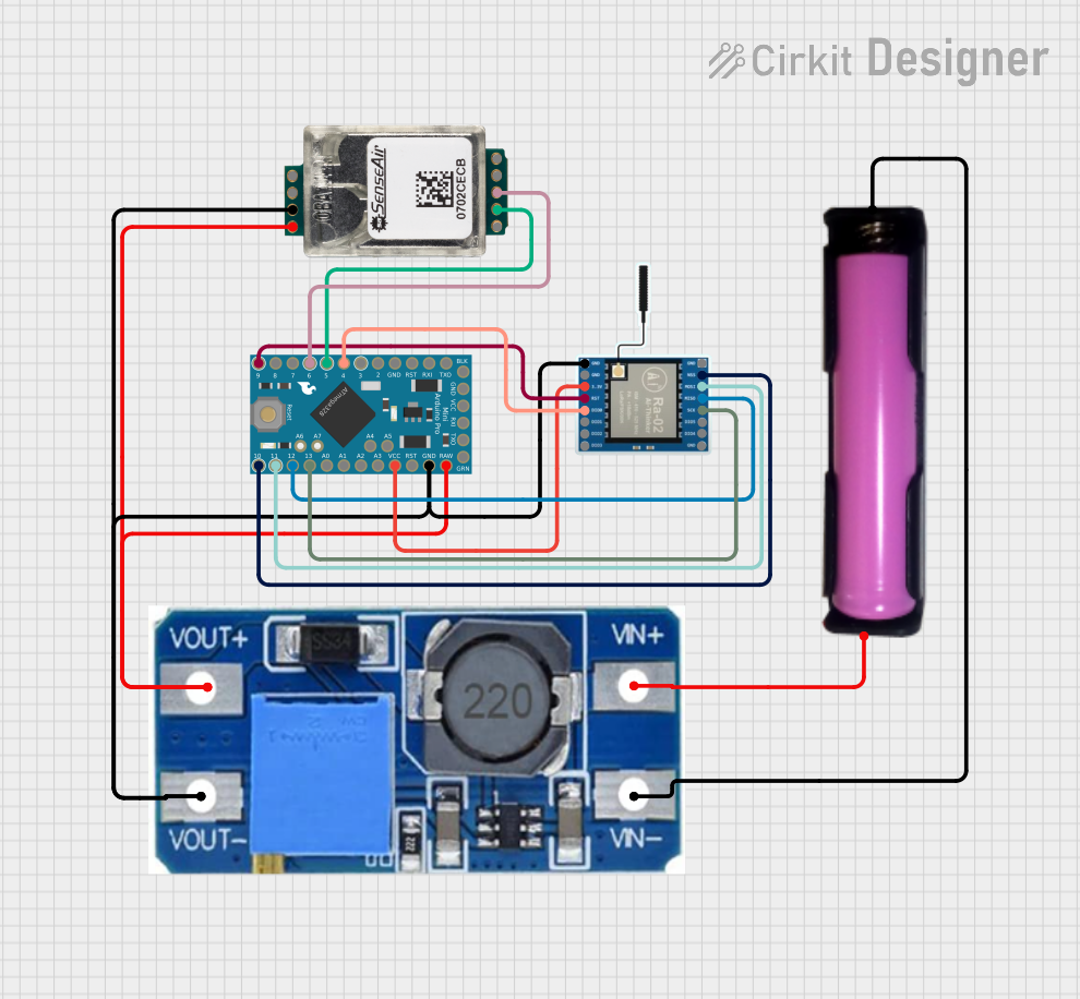
This circuit is designed to monitor CO2 levels using the SenseAir S8 CO2 Sensor and transmit the data wirelessly via a LoRa Ra-02 SX1278 module. The core controller of the circuit is an Arduino Pro Mini, which interfaces with both the CO2 sensor and the LoRa module. A Step Up Boost Power Converter is used to regulate the voltage supplied to the Arduino and the CO2 sensor. The power source for the circuit is a single 18650 battery in a holder.
Component List
SenseAir S8 CO2 Sensor
- Description: A carbon dioxide sensor module designed for HVAC control and indoor air quality monitoring.
- Pins: G+, G0, Alarm OC, PWM 1kHz, DVCC out, RX, TX, R/T, CAL
Step Up Boost Power Converter, Adjustable Voltage Regulator
- Description: A voltage regulator that steps up the input voltage to a higher, adjustable output voltage.
- Pins: VOUT+, VOUT-, VIN+, VIN-
18650 Battery in Holder
- Description: A rechargeable lithium-ion cell commonly used in high-drain applications.
- Pins: GND, VCC
Arduino Pro Mini
- Description: A small, complete, breadboard-friendly microcontroller board based on the ATmega328.
- Pins: DTR, TXO, RXI, VCC, GND, A4, A5, RAW, RESET, A3, A2, A1, A0, SCK, MISO, MOSI, D10, D9, D8, D7, D6, D5, D4, D3, D2
LoRa Ra-02 SX1278
- Description: A wireless communication module that uses LoRa technology for long-range, low-power communication.
- Pins: GND, NSS, MOSI, MISO, SCK, D105, DI04, 3.3V, RST, DI00, DI01, D102, DI03
Wiring Details
SenseAir S8 CO2 Sensor
- G+ connected to VOUT+ of the Step Up Boost Power Converter
- G0 connected to VOUT- of the Step Up Boost Power Converter
- RX connected to D5 of the Arduino Pro Mini
- TX connected to D6 of the Arduino Pro Mini
Step Up Boost Power Converter, Adjustable Voltage Regulator
- VOUT+ connected to RAW of the Arduino Pro Mini and G+ of the SenseAir S8 CO2 Sensor
- VOUT- connected to GND of the Arduino Pro Mini, GND of the LoRa Ra-02 SX1278, and G0 of the SenseAir S8 CO2 Sensor
- VIN+ connected to VCC of the 18650 Battery in Holder
- VIN- connected to GND of the 18650 Battery in Holder
18650 Battery in Holder
- VCC connected to VIN+ of the Step Up Boost Power Converter
- GND connected to VIN- of the Step Up Boost Power Converter
Arduino Pro Mini
- RAW connected to VOUT+ of the Step Up Boost Power Converter
- GND connected to VOUT- of the Step Up Boost Power Converter
- VCC connected to 3.3V of the LoRa Ra-02 SX1278
- D5 connected to RX of the SenseAir S8 CO2 Sensor
- D6 connected to TX of the SenseAir S8 CO2 Sensor
- SCK connected to SCK of the LoRa Ra-02 SX1278
- MISO connected to MISO of the LoRa Ra-02 SX1278
- MOSI connected to MOSI of the LoRa Ra-02 SX1278
- D10 connected to NSS of the LoRa Ra-02 SX1278
- D9 connected to RST of the LoRa Ra-02 SX1278
- D4 connected to DI00 of the LoRa Ra-02 SX1278
LoRa Ra-02 SX1278
- GND connected to VOUT- of the Step Up Boost Power Converter
- 3.3V connected to VCC of the Arduino Pro Mini
- SCK connected to SCK of the Arduino Pro Mini
- MISO connected to MISO of the Arduino Pro Mini
- MOSI connected to MOSI of the Arduino Pro Mini
- NSS connected to D10 of the Arduino Pro Mini
- RST connected to D9 of the Arduino Pro Mini
- DI00 connected to D4 of the Arduino Pro Mini
Documented Code
/*
 * Arduino Sketch for CO2 Monitoring and LoRa Transmission
 *
 * This code reads CO2 levels from the SenseAir S8 CO2 Sensor and transmits the
 * data wirelessly using the LoRa Ra-02 SX1278 module. The Arduino Pro Mini is
 * used as the microcontroller to interface with both the sensor and the LoRa
 * module.
 */

#include <SoftwareSerial.h>
#include <SPI.h>
#include <LoRa.h>

// Pin definitions
#define CO2_RX_PIN 5
#define CO2_TX_PIN 6
#define LORA_RST_PIN 9
#define LORA_SS_PIN 10
#define LORA_DIO0_PIN 4

// Create a SoftwareSerial object for CO2 sensor communication
SoftwareSerial co2Serial(CO2_RX_PIN, CO2_TX_PIN);

void setup() {
  // Initialize serial communication for debugging
  Serial.begin(9600);
  while (!Serial);
  Serial.println("CO2 Monitoring and LoRa Transmission");

  // Initialize SoftwareSerial for CO2 sensor
  co2Serial.begin(9600);

  // Initialize LoRa module
  LoRa.setPins(LORA_SS_PIN, LORA_RST_PIN, LORA_DIO0_PIN);
  if (!LoRa.begin(915E6)) {
    Serial.println("Starting LoRa failed!");
    while (1);
  }
  Serial.println("LoRa Initializing OK!");
}

void loop() {
  // Read CO2 concentration from the sensor
  int co2Concentration = readCO2();
  Serial.print("CO2 Concentration: ");
  Serial.print(co2Concentration);
  Serial.println(" ppm");

  // Transmit CO2 concentration via LoRa
  LoRa.beginPacket();
  LoRa.print(co2Concentration);
  LoRa.endPacket();

  // Wait for a minute before the next reading
  delay(60000);
}

int readCO2() {
  // Send command to read CO2 concentration
  byte cmd[] = {0xFE, 0x44, 0x00, 0x08, 0x02, 0x9F, 0x25};
  co2Serial.write(cmd, 7);
  co2Serial.flush();

  // Wait for the sensor to respond
  delay(10);

  // Read the response
  byte response[7];
  co2Serial.readBytes(response, 7);

  // Calculate CO2 concentration
  int high = response[3];
  int low = response[4];
  int co2 = (high << 8) + low;

  return co2;
}
This code is responsible for initializing the communication with the CO2 sensor and the LoRa module, reading the CO2 concentration, and transmitting the data wirelessly. The readCO2 function sends a command to the CO2 sensor to get the current CO2 concentration and then reads the response to calculate the concentration value. The main loop transmits the CO2 concentration via LoRa and waits for a minute before taking the next reading.