
ESP8266-Based Multi-Sensor Monitoring System with Alert and Actuator Control
View and Edit Project In Cirkit Designer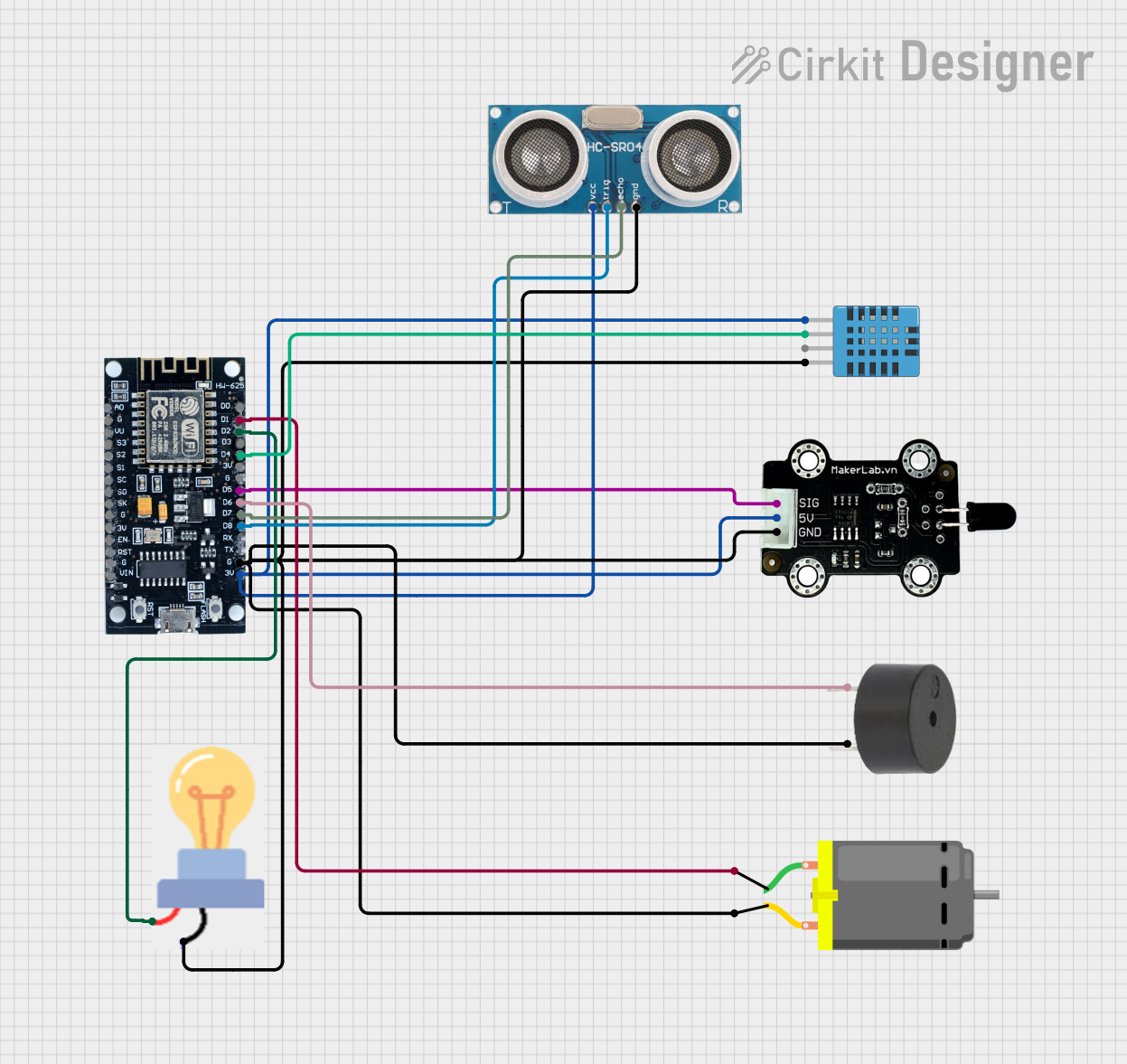
Circuit Documentation
Summary
The circuit in question appears to be a multi-sensor system with an ESP8266 microcontroller at its core. The system includes an ultrasonic sensor for distance measurement, a DHT11 sensor for humidity and temperature readings, a bulb and a DC motor for output devices, a buzzer for audio signaling, and an MKE-S04 IR Infrared Flame Sensor for detecting flames. The ESP8266 microcontroller is responsible for interfacing with these sensors and actuators, processing their signals, and presumably, based on the absence of code, controlling the outputs based on sensor inputs.
Component List
ESP8266
- Description: A popular Wi-Fi microcontroller module that can be used for a variety of IoT applications.
- Pins: 3V, G, D8, D7, D6, D5, D4, D3, D2, D1, D0, A0, S3, S2, S1, SC, S0, SK, EN, VIN, RST, VU
Ultrasonic Sensor
- Description: A sensor that measures distance by emitting ultrasonic waves and measuring the time taken for the echo to return.
- Pins: +VCC, Trigger, Echo, GND
DHT11 Humidity and Temperature Sensor
- Description: A sensor that provides ambient humidity and temperature readings.
- Pins: VDD, DATA, NULL, GND
Bulb
- Description: An electric light source.
- Pins: GND, power
DC Motor
- Description: An electric motor that runs on direct current (DC) electricity.
- Pins: pin 1, pin 2
MKE-S04 IR Infrared Flame Sensor
- Description: A sensor that detects the presence of flames or fire by sensing infrared light emitted by the flames.
- Pins: SIG, 5V, GND
Buzzer
- Description: An audio signaling device that can produce a range of sound frequencies.
- Pins: PIN, GND
Wiring Details
ESP8266
- 3V connected to Ultrasonic Sensor VCC, DHT11 VDD, and MKE-S04 5V
- G connected to common ground with Ultrasonic Sensor GND, DHT11 GND, Bulb GND, MKE-S04 GND, Buzzer GND, and DC Motor pin 2
- D8 connected to Ultrasonic Sensor Trigger
- D7 connected to Ultrasonic Sensor Echo
- D6 connected to Buzzer PIN
- D5 connected to MKE-S04 SIG
- D4 connected to DHT11 DATA
- D2 connected to Bulb power
- D1 connected to DC Motor pin 1
Ultrasonic Sensor
- +VCC connected to ESP8266 3V
- Trigger connected to ESP8266 D8
- Echo connected to ESP8266 D7
- GND connected to common ground
DHT11 Humidity and Temperature Sensor
- VDD connected to ESP8266 3V
- DATA connected to ESP8266 D4
- GND connected to common ground
Bulb
- power connected to ESP8266 D2
- GND connected to common ground
DC Motor
- pin 1 connected to ESP8266 D1
- pin 2 connected to common ground
MKE-S04 IR Infrared Flame Sensor
- SIG connected to ESP8266 D5
- 5V connected to ESP8266 3V
- GND connected to common ground
Buzzer
- PIN connected to ESP8266 D6
- GND connected to common ground
Documented Code
No code has been provided for the microcontroller. The expected behavior of the system, based on the wiring, would be for the ESP8266 to read data from the sensors, control the bulb and DC motor as outputs, and signal with the buzzer based on certain conditions. The code would typically initialize the sensors, set up the GPIO pins, and contain a main loop that handles sensor readings and output control. Since no code is available, it is not possible to provide further documentation on the software aspect of this circuit.