
Arduino Nano Controlled Ultrasonic Distance Measurement with CAN Bus Interface and I2C LCD Display
View and Edit Project In Cirkit Designer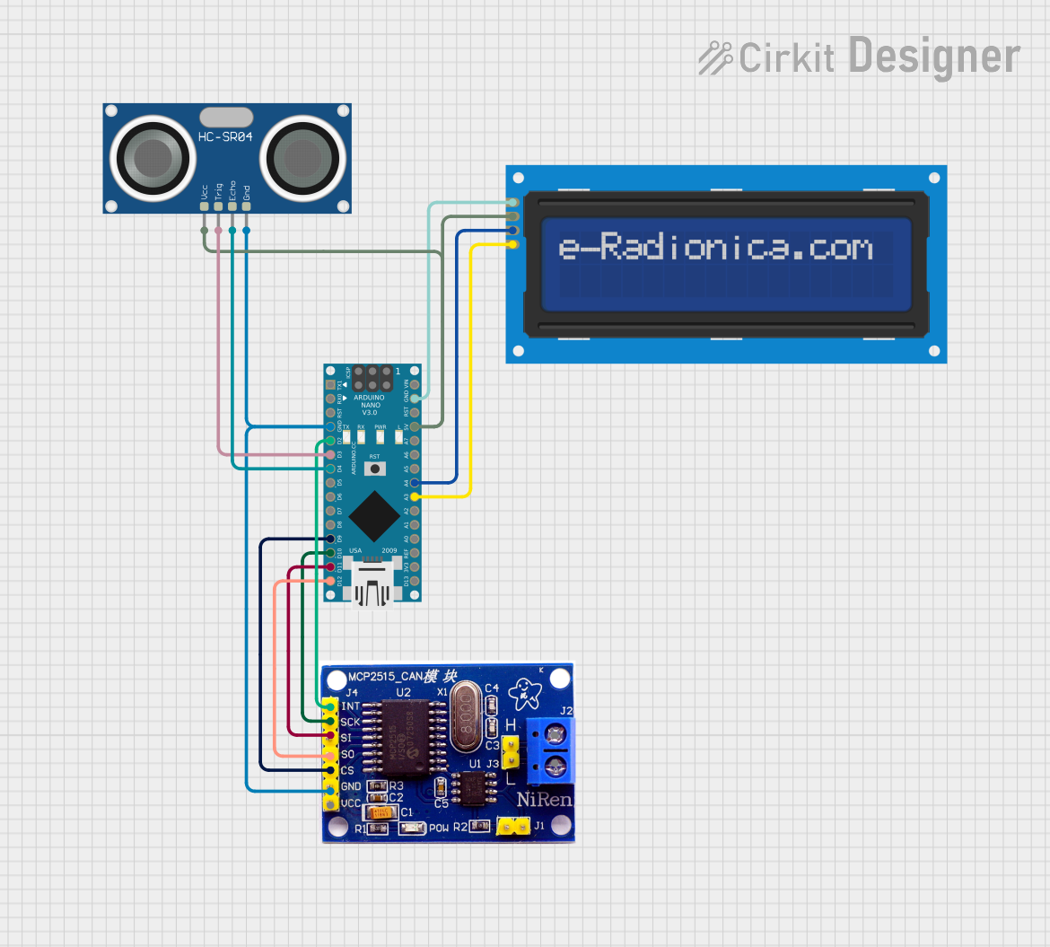
Circuit Documentation
Summary
The circuit in question is designed to interface an Arduino Nano with several peripheral devices, including an MCP2515 CAN controller, an LCD screen with I2C interface, and an HC-SR04 ultrasonic sensor. The Arduino Nano serves as the central processing unit, managing communication between the CAN network and the user interface provided by the LCD screen, as well as capturing distance measurements from the ultrasonic sensor. The circuit is powered by the Arduino Nano's 5V output, which is distributed to the other components.
Component List
MCP2515 CAN Controller
- Description: A stand-alone Controller Area Network (CAN) controller that implements the CAN specification, version 2.0B. It is capable of transmitting and receiving both standard and extended data and remote frames.
- Pins: INT, SCK, SI, SO, CS, GND, VCC, H, L
Arduino Nano
- Description: A small, complete, and breadboard-friendly board based on the ATmega328P. It offers the same connectivity and specs of the UNO board in a smaller form factor.
- Pins: D1/TX, D0/RX, RESET, GND, D2, D3, D4, D5, D6, D7, D8, D9, D10, D11/MOSI, D12/MISO, VIN, 5V, A7, A6, A5, A4, A3, A2, A1, A0, AREF, 3V3, D13/SCK
LCD Screen 16x2 I2C
- Description: A 16x2 character LCD display equipped with an I2C interface, which reduces the number of pins needed for operation.
- Pins: SCL, SDA, VCC, GND
HC-SR04 Ultrasonic Sensor
- Description: An ultrasonic distance sensor capable of measuring distances from 2cm to 400cm with an accuracy of 3mm.
- Pins: VCC, TRIG, ECHO, GND
Wiring Details
MCP2515 CAN Controller
- INT connected to Arduino Nano D2
- SCK connected to Arduino Nano D13/SCK
- SI connected to Arduino Nano D11/MOSI
- SO connected to Arduino Nano D12/MISO
- CS connected to Arduino Nano D9
- GND connected to common ground
- VCC connected to Arduino Nano 5V
Arduino Nano
- GND connected to common ground
- 5V connected to VCC of MCP2515, LCD screen, and HC-SR04
- D2 connected to INT of MCP2515
- D3 connected to TRIG of HC-SR04
- D4 connected to ECHO of HC-SR04
- D9 connected to CS of MCP2515
- D10 connected to SCK of MCP2515
- D11/MOSI connected to SI of MCP2515
- D12/MISO connected to SO of MCP2515
- A4 connected to SDA of LCD screen
- A3 connected to SCL of LCD screen
LCD Screen 16x2 I2C
- SCL connected to Arduino Nano A3
- SDA connected to Arduino Nano A4
- VCC connected to Arduino Nano 5V
- GND connected to common ground
HC-SR04 Ultrasonic Sensor
- VCC connected to Arduino Nano 5V
- TRIG connected to Arduino Nano D3
- ECHO connected to Arduino Nano D4
- GND connected to common ground
Documented Code
/**************I2C LCD display****************/
#include <LiquidCrystal_I2C.h>

LiquidCrystal_I2C lcd(0x20, 16, 2); // Format -> (Address,Width,Height )

/**********************CAN Communication************************************************/

#include <SPI.h>
#define SERIAL Serial
#define CAN_2515

#include "mcp2515_can.h"
const int SPI_CS_PIN = 10;
const int CAN_INT_PIN = 2;
mcp2515_can CAN(SPI_CS_PIN); // Set CS pin
unsigned char stmp[8] = {0, 0, 0, 0, 0, 0, 0, 0};

/**************HC-SR04 Ultrasonic Sensor****************/

#define trigPin 3 //attach pin D3 Arduino to pin Trig of HC-SR04
#define echoPin 4 // attach pin D4 Arduino to pin Echo of HC-SR04

// defines variables
long duration; // variable for the duration of sound wave travel
int distance; // variable for the distance measurement

void setup() {
    // Initialize I2C LCD display
    lcd.init();         // initialize the lcd
    lcd.backlight();    // Turn on the Backlight
    // Initialize ultrasonic sensor
    pinMode(trigPin, OUTPUT);  // Sets the trigPin as an OUTPUT
    pinMode(echoPin, INPUT);    // Sets the echoPin as an INPUT
    Serial.begin(9600);        // Serial Communication is starting with 9600 of baud rate speed
    Serial.println("Ultrasonic Sensor HC-SR04 Test"); // print some text in Serial Monitor
    Serial.println("with Arduino NANO");
    // Initialize CAN communication
    while (CAN_OK != CAN.begin(CAN_500KBPS)) {             // init can bus : baudrate = 500k
        SERIAL.println("CAN BUS Shield init fail");
        SERIAL.println(" Init CAN BUS Shield again");
        delay(100);
    }
    SERIAL.println("CAN BUS Shield init ok!");

}
void loop() {

    lcd.clear();            // Clear the display buffer
    lcd.setCursor(0, 0);    // Set cursor (Column, Row)
    lcd.print("Response:");   // print "Response:" at (0, 0)
    lcd.setCursor(0,1);     // Set cursor (Column, Row)
    lcd.print("Distance:");    // print "Distance:" at (0, 1)


    digitalWrite(trigPin, LOW);     // Clears the trigPin condition
    delayMicroseconds(2);           // Sets the trigPin HIGH (ACTIVE) for 1000 microseconds
    digitalWrite(trigPin, HIGH);
    delayMicroseconds(1000);
    digitalWrite(trigPin, LOW);

    duration = pulseIn(echoPin, HIGH);      // Reads the echoPin, returns the sound wave travel time in microseconds
                                            // Calculating the distance
    distance = duration * 0.034 / 2;        // Speed of sound wave divided by 2 (go and back)
                                            // Displays the distance on the Serial Monitor
    Serial.print("Distance: ");
    Serial.print(distance);
    Serial.println(" cm");
    lcd.setCursor(8, 0);    // Set cursor (Column, Row)
    lcd.print(duration);   // print response time at (8, 0)
    lcd.setCursor(12,1);     // Set cursor (Column, Row)
    lcd.print(distance);    // print "Distance:" at (12, 1)


    // send data:  id = 0x00, standard frame, data len = 8, stmp: data buf
    stmp[7] = stmp[7] + 1;
    if (stmp[7] == 100) {
        stmp[7] = 0;
        stmp[6] = stmp[6] + 1;

        if (stmp[6] == 100) {
            stmp[6] = 0;
            stmp[5] = stmp[6] + 1;
        }
    }

    CAN.sendMsgBuf(0x00, 0, 8, stmp);
    delay(100);                       // send data per 100ms
    SERIAL.println("CAN BUS sendMsgBuf ok!");
}
This code is responsible for initializing and managing the LCD display, ultrasonic sensor, and CAN communication. It includes setup routines for each component and a loop that continuously measures distance, updates the LCD display, and sends data over the CAN bus.