Arduino UNO Controlled Weather Monitoring System with Dual Servomotors and Rain Sensor

Circuit Documentation
Summary of the Circuit
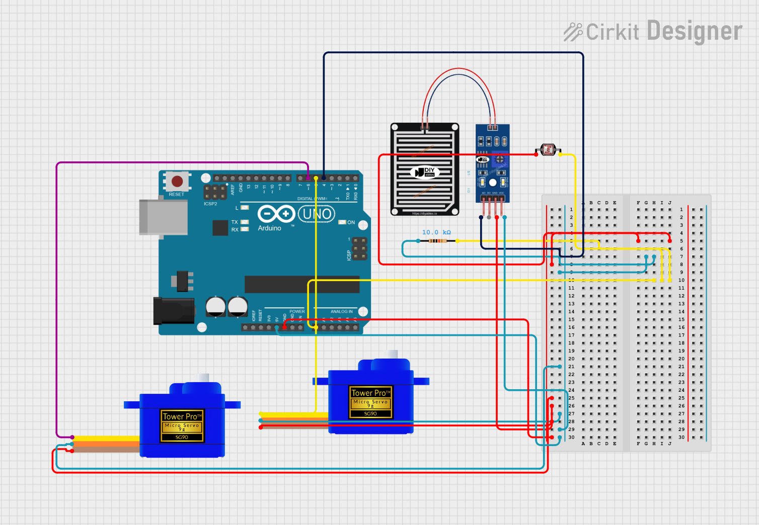
This circuit appears to be designed for environmental sensing and actuation. It includes a microcontroller (Arduino UNO), two servomotors (SG90), a rain sensor, a photocell (LDR), and a resistor. The Arduino UNO is used as the central processing unit, interfacing with the rain sensor and photocell to receive environmental data, and controlling the servomotors based on this data. The resistor is likely used for creating a voltage divider with the photocell to measure light levels.
Component List
Resistor
- Description: A passive two-terminal electrical component that implements electrical resistance as a circuit element.
- Properties: 10,000 Ohms resistance.
Arduino UNO
- Description: A microcontroller board based on the ATmega328P. It has 14 digital input/output pins, 6 analog inputs, a 16 MHz quartz crystal, a USB connection, a power jack, an ICSP header, and a reset button.
Rain Sensor
- Description: A weather sensor capable of detecting rain. It usually comes with an analog output (AO) and a digital output (DO).
Servomotor SG90
- Description: A small and lightweight servo that is used for precise control of angular or linear position, velocity, and acceleration.
Photocell (LDR)
- Description: A light-dependent resistor whose resistance decreases with increasing incident light intensity. It can be used to detect light levels.
Wiring Details
Resistor
- One end connected to Arduino UNO's analog input A0.
- The other end connected to the photocell.
Arduino UNO
- Ground (GND) connected to the ground pins of the servomotors, rain sensor, and photocell.
- 5V output supplying power to the servomotors and rain sensor.
- Analog input A0 connected to the resistor and photocell to form a voltage divider for light sensing.
- Digital output D6 connected to the signal pin of one servomotor.
- Digital output D5 connected to the signal pin of the other servomotor.
- Digital output D4 connected to the analog output of the rain sensor.
Rain Sensor
- Analog output (AO) connected to Arduino UNO's digital input D4.
- Power (VCC) and ground (GRD) connected to Arduino UNO's 5V and GND, respectively.
Servomotor SG90
- Signal (SIG) pin of one servomotor connected to Arduino UNO's digital output D6.
- Signal (SIG) pin of the other servomotor connected to Arduino UNO's digital output D5.
- Power (VCC) and ground (GND) pins connected to Arduino UNO's 5V and GND, respectively.
Photocell (LDR)
- One pin connected to the resistor and Arduino UNO's analog input A0.
- The other pin connected to the common ground.
Documented Code
void setup() {
  // put your setup code here, to run once:

}

void loop() {
  // put your main code here, to run repeatedly:

}
The provided code is a template with empty setup() and loop() functions. The setup() function is intended for initialization code that runs once when the microcontroller is powered on or reset. The loop() function contains the main logic of the program, which runs repeatedly as long as the microcontroller is powered.
Further implementation details would be required to provide a functional program, such as initializing the input and output pins, reading sensor data, and controlling the servomotors based on sensor inputs.