Cirkit Designer
Your all-in-one circuit design IDE
Home /
Project Documentation
Arduino-Controlled Obstacle-Avoiding Robot with Bluetooth and Ultrasonic Sensor
Circuit Documentation
Summary
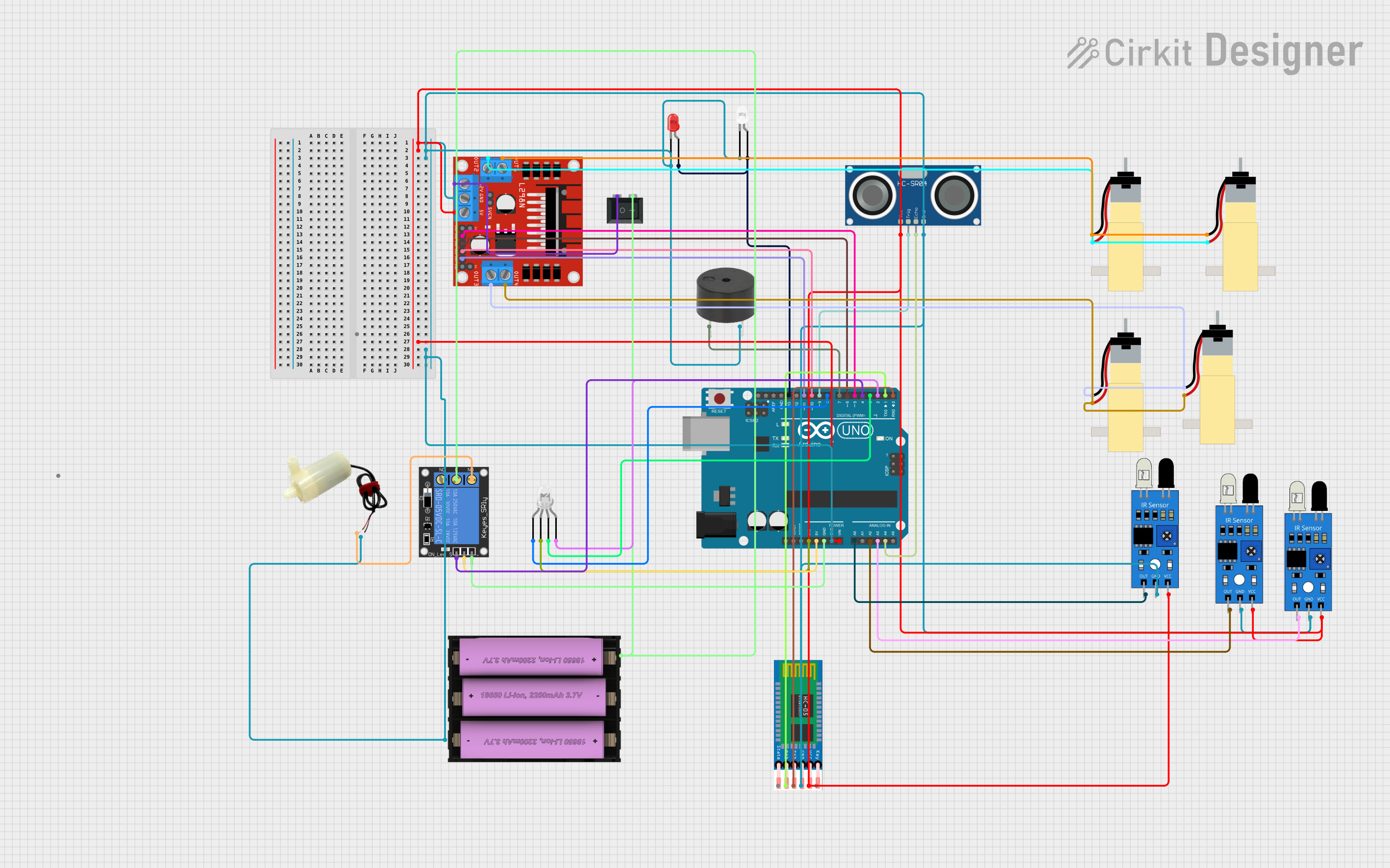
This circuit is designed to control a variety of components including motors, sensors, and actuators using an Arduino UNO as the central microcontroller. The circuit features motor drivers for controlling gearmotors, an ultrasonic sensor for distance measurement, IR sensors for object detection, a Bluetooth module for wireless communication, LEDs for visual feedback, a buzzer for audio alerts, a relay for controlling a water pump, and a switch for power control. The system is powered by an 11.1V Li-ion battery.
Component List
5v Mini Water Pump
- A small water pump that operates at 5 volts.
Arduino UNO
- A microcontroller board based on the ATmega328P, with a variety of digital and analog I/O pins.
HC-SR04 Ultrasonic Sensor
- An ultrasonic distance sensor that can measure distances by emitting and receiving ultrasonic waves.
HC-05 Bluetooth Module
- A Bluetooth module for wireless communication with other devices.
LEDs (Red and White)
- Light-emitting diodes used for visual indication.
L298N DC Motor Driver
- A motor driver module capable of driving up to two DC motors with direction and speed control.
Buzzer
- An electronic buzzer for audio alerts.
Li-ion Battery, 2200 mAh 11.1 V
- A rechargeable lithium-ion battery providing the power source for the circuit.
Hobby Gearmotors with 48:1 Gearbox (4 units)
- DC gearmotors used for driving mechanical parts.
IR Sensors (3 units)
- Infrared sensors used for object detection.
Rocker Switch (SPST)
- A single-pole single-throw switch used for turning the power on and off.
LED: Four Pin (RGB)
- A four-pin RGB LED capable of displaying multiple colors.
1-Channel Relay (5V 10A)
- A relay module for controlling high-power devices such as the water pump.
Wiring Details
5v Mini Water Pump
- Positive Pin: Connected to the Normally Open (NO) terminal of the relay.
- Negative Pin: Connected to the common ground net.
Arduino UNO
- Vin: Connected to the 5V net.
- 3.3V: Connected to the common anode of the four-pin LED.
- 5V: Connected to the power terminal of the relay.
- GND: Connected to the ground terminal of the relay and common ground net.
- A0-A4: Connected to the output pins of the IR sensors and the echo pin of the ultrasonic sensor.
- D0-D13: Connected to various components including the HC-05 Bluetooth module, LEDs, buzzer, motor driver inputs, and relay signal pin.
HC-SR04 Ultrasonic Sensor
- VCC: Connected to the 5V net.
- TRIG: Connected to pin D9 of the Arduino UNO.
- ECHO: Connected to pin A4 of the Arduino UNO.
- GND: Connected to the common ground net.
HC-05 Bluetooth Module
- EN: Not connected in this circuit.
- VCC: Connected to the 5V net.
- GND: Connected to the common ground net.
- TXD: Connected to pin D0 (RX) of the Arduino UNO.
- RXD: Connected to pin D1 (TX) of the Arduino UNO.
- STATE: Not connected in this circuit.
LEDs (Red and White)
- Cathode: Connected to the common ground net.
- Anode (Red LED): Connected to pin D13 of the Arduino UNO.
- Anode (White LED): Connected to pin D13 of the Arduino UNO.
L298N DC Motor Driver
- OUT1-OUT4: Connected to the pins of the hobby gearmotors.
- 12V: Connected to one terminal of the rocker switch.
- GND: Connected to the common ground net.
- 5V: Connected to the 5V net.
- ENA, ENB: Not connected in this circuit.
- IN1-IN4: Connected to pins D5-D11 of the Arduino UNO.
Buzzer
- PIN: Connected to pin D7 of the Arduino UNO.
- GND: Connected to the common ground net.
Li-ion Battery, 2200 mAh 11.1 V
- Positive (+): Connected to one terminal of the rocker switch and the common terminal (C) of the relay.
- Negative (-): Connected to the common ground net.
Hobby Gearmotors with 48:1 Gearbox
- Pin 1 and Pin 2: Connected to the OUT1-OUT4 of the L298N motor driver.
IR Sensors
- Out: Connected to pins A0-A3 of the Arduino UNO.
- GND: Connected to the common ground net.
- VCC: Connected to the 5V net.
Rocker Switch (SPST)
- Terminal 1: Connected to the 12V input of the motor driver.
- Terminal 2: Connected to the positive terminal of the battery.
LED: Four Pin (RGB)
- Red Cathode: Connected to pin D8 of the Arduino UNO.
- Common Anode: Connected to the 3.3V pin of the Arduino UNO.
- Green Cathode: Connected to pin D3 of the Arduino UNO.
- Blue Cathode: Connected to pin D2 of the Arduino UNO.
1-Channel Relay (5V 10A)
- NC: Not connected in this circuit.
- Signal: Connected to pin D4 of the Arduino UNO.
- C: Connected to the positive terminal of the battery.
- Power: Connected to the 5V pin of the Arduino UNO.
- NO: Connected to the positive pin of the water pump.
- Ground: Connected to the common ground net.
Documented Code
#define in1 5 //L298n Motor Driver pins.
#define in2 6
#define in3 10
#define in4 11
#define EXTRA 4
const int trigPin = 9;
const int echoPin = 18;
long duration;
int distance;
#define light_FR  13    //LED Front Right   pin A0 for Arduino Uno
//#define light_FL  15   //LED Front Left    pin A1 for Arduino Uno
#define light_BR  12    //LED Back Right    pin A2 for Arduino Uno
//#define light_BL  17    //LED Back Left     pin A3 for Arduino Uno
#define horn_Buzz 7    //Horn Buzzer       pin A4 for Arduino Uno
int command; //Int to store app command state.
int Speed = 204; // 0 - 255.
int Speedsec;
int buttonState = 0;
int lastButtonState = 0;
int Turnradius = 0; //Set the radius of a turn, 0 - 255 Note:the robot will malfunction if this is higher than int Speed.
int brakeTime = 45;
int brkonoff = 1; //1 for the electronic braking system, 0 for normal.
boolean lightFront = false;
boolean lightBack = false;
boolean horn = false;
boolean extra = false;

void setup() {
  pinMode(trigPin, OUTPUT); // Sets the trigPin as an Output
  pinMode(echoPin, INPUT);
  pinMode(EXTRA,OUTPUT);
  pinMode(in1, OUTPUT);
  pinMode(in2, OUTPUT);
  pinMode(in3, OUTPUT);
  pinMode(in4, OUTPUT);
  pinMode(14,INPUT);
  pinMode(light_FR, OUTPUT);
 //   pinMode(light_FL, OUTPUT);
  pinMode(light_BR, OUTPUT);
 //   pinMode(light_BL, OUTPUT);
  pinMode(horn_Buzz, OUTPUT);

  Serial.begin(9600);  //Set the baud rate to your Bluetooth module.
}

void loop() {
  digitalWrite(trigPin, LOW);
  delayMicroseconds(2);
  // Sets the trigPin on HIGH state for 10 micro seconds
  digitalWrite(trigPin, HIGH);
  delayMicroseconds(10);
  digitalWrite(trigPin, LOW);
  // Reads the echoPin, returns the sound wave travel time in microseconds
  duration = pulseIn(echoPin, HIGH);
  // Calculating the distance
  distance = duration * 0.034 / 2;
  // Prints the distance on the Serial Monitor
  Serial.println(distance);
  if(distance<25){Stop();
  delay(100);
   digitalWrite(in1,LOW);
    digitalWrite(in2,HIGH);
     digitalWrite(in3,LOW);
      digitalWrite(in4,HIGH);
      delay(500);
      digitalWrite(in1,LOW);
    digitalWrite(in2,LOW);
     digitalWrite(in3,LOW);
      digitalWrite(in4,LOW);
   }
   if(distance<25){digitalWrite(horn_Buzz,1);
   delay(50);
   digitalWrite(horn_Buzz,0);
delay(50);
digitalWrite(horn_Buzz,1);
   delay(50);
   digitalWrite(horn_Buzz,0);
delay(50);
digitalWrite(horn_Buzz,1);
   delay(50);
   digitalWrite(horn_Buzz,0);
   }
   //FRONT IR 1
    if (digitalRead(14)== HIGH){Stop();
  delay(100);
   digitalWrite(in1,LOW);
    digitalWrite(in2,HIGH);
     digitalWrite(in3,LOW);
      digitalWrite(in4,HIGH);
      delay(300);
      digitalWrite(in1,