ESP8266 NodeMCU Controlled Smart Relay with IR and Temperature Sensing
Circuit Documentation
Summary of the Circuit
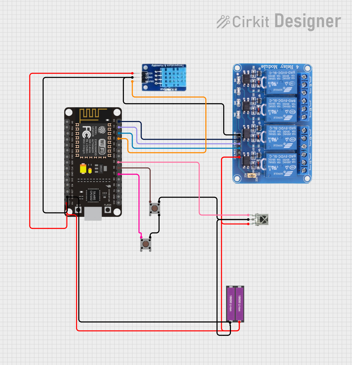
This circuit is designed to control a 4-channel relay module using an ESP8266 NodeMCU microcontroller. The circuit includes input devices such as a DHT11 temperature and humidity sensor, a VS1838B infrared (IR) receiver, and two pushbuttons for user interaction. The ESP8266 NodeMCU is responsible for processing the inputs from the DHT11 sensor, the IR receiver, and the pushbuttons to control the state of the relay channels. The relay module can be used to switch higher power loads that the ESP8266 cannot directly control. The circuit is powered by two 18650 Li-ion batteries connected in series or parallel (not specified), providing power to the microcontroller, the relay module, the sensor, and the IR receiver.
Component List
ESP8266 NodeMCU
- Microcontroller module with WiFi capability.
- Provides GPIO pins for interfacing with other components.
18650 Li-ion Battery x 2
- Power source for the circuit.
- Provides the necessary voltage and current to drive the components.
VS1838B IR Receiver
- Infrared receiver for remote control applications.
- Outputs a signal when it receives an IR command.
Relay 4 Channel 5v
- Relay module with 4 channels.
- Allows for controlling high power devices.
DHT11
- Temperature and humidity sensor.
- Provides digital signal output with environmental data.
Pushbutton (x2)
- Simple pushbutton switch for user input.
- Can be used to trigger events or actions in the circuit.
Wiring Details
ESP8266 NodeMCU
D0connected to Relay 4 ChannelIN1D1connected to Relay 4 ChannelIN2D2connected to Relay 4 ChannelIN3D3connected to DHT11DATAD5connected to VS1838B IR ReceiverOUTD6connected to Pushbutton 1Pin 1 (in)D7connected to Pushbutton 2Pin 1 (in)GNDconnected to common ground netVINconnected to common VCC net
18650 Li-ion Battery x 2
+connected to common VCC net-connected to common ground net
VS1838B IR Receiver
OUTconnected to ESP8266 NodeMCUD5GNDconnected to common ground netVCCconnected to common VCC net
Relay 4 Channel 5v
IN1,IN2,IN3connected to ESP8266 NodeMCUD0,D1,D2respectivelyGNDconnected to common ground netVCCconnected to common VCC net
DHT11
DATAconnected to ESP8266 NodeMCUD3GNDconnected to common ground netVCCconnected to common VCC net
Pushbutton 1
Pin 1 (in)connected to ESP8266 NodeMCUD6Pin 3 (out)connected to common ground net
Pushbutton 2
Pin 1 (in)connected to ESP8266 NodeMCUD7Pin 3 (out)connected to common ground net
Documented Code
No code was provided for the microcontroller. The expected functionality would include reading the state of the DHT11 sensor and the IR receiver, debouncing the pushbuttons, and controlling the relay channels based on the inputs. The code would also handle any WiFi communication if the ESP8266 NodeMCU is used for remote control or data reporting.