Cirkit Designer
Your all-in-one circuit design IDE
Home /
Project Documentation
Raspberry Pi Zero W Smart Motion and Tap Switch Sensor System
Circuit Documentation
Summary
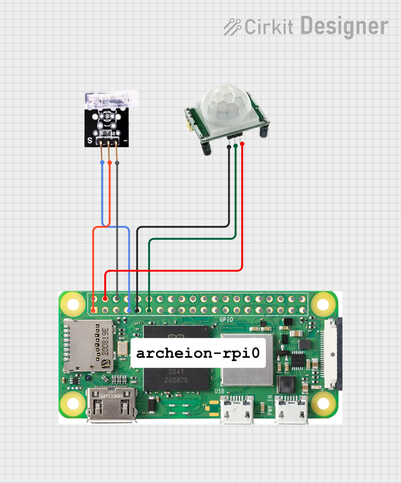
This circuit involves a Raspberry Pi Zero W, a Tap Switch, and an HC-SR501 sensor. The Raspberry Pi Zero W serves as the central controller, interfacing with the Tap Switch and the HC-SR501 sensor to perform various functions. The Tap Switch is used for user input, while the HC-SR501 sensor is used for motion detection.
Component List
Raspberry Pi Zero W
- Description: A small, affordable computer that you can use for a variety of electronics projects.
- Pins:
- 5V
- 3V3
- GPIO2 (SDA)
- GPIO 3
- GROUND
- GPIO 14
- GPIO15
- GPIO 18
- GND
- GPIO 23
- GPIO24
- GPIO 25
- GPIO 8
- GPIO 7
- GPIO 1
- GPIO 12
- GPIO 16
- GPIO 20
- GPIO 21
- GPIO 04
- GPIO 17
- GPIO 27
- GPIO 22
- GPIO 10
- GPIO 9
- GPIO 11
- GPIO 0
- GPIO 5
- GPIO 6
- GPIO 13
- GPIO 19
- GPIO 26
- CSI (CAMERA)
Tap Switch
- Description: A switch that can be activated by tapping.
- Pins:
- GND
- VCC
- OUTPUT
HC-SR501
- Description: A motion sensor that detects infrared radiation.
- Pins:
- GND
- OUTPUT
- VCC
Comment
- Description: A placeholder for comments or notes.
- Pins: None
Wiring Details
Raspberry Pi Zero W
- 5V is connected to VCC of the HC-SR501.
- 3V3 is connected to VCC of the Tap Switch.
- GROUND is connected to GND of the Tap Switch.
- GND is connected to GND of the HC-SR501.
- GPIO 04 is connected to OUTPUT of the Tap Switch.
- GPIO 17 is connected to OUTPUT of the HC-SR501.
Tap Switch
- VCC is connected to 3V3 of the Raspberry Pi Zero W.
- GND is connected to GROUND of the Raspberry Pi Zero W.
- OUTPUT is connected to GPIO 04 of the Raspberry Pi Zero W.
HC-SR501
- VCC is connected to 5V of the Raspberry Pi Zero W.
- GND is connected to GND of the Raspberry Pi Zero W.
- OUTPUT is connected to GPIO 17 of the Raspberry Pi Zero W.
Code
There is no code provided for the microcontrollers in this circuit.
This documentation provides a comprehensive overview of the circuit, including a summary, detailed component list, wiring details, and code documentation.