
Circuit Documentation
Summary
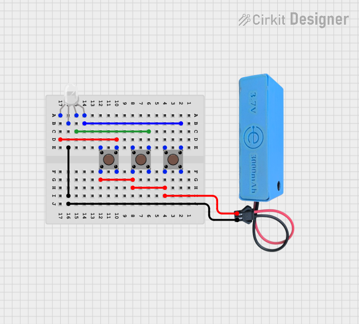
This circuit consists of an RGB LED and three pushbuttons, powered by a MAHIR 1.mini power source. Each pushbutton controls one of the RGB LED's color channels (Red, Green, and Blue). The common pin of the RGB LED is connected to the ground of the power source.
Component List
RGB LED (Wokwi compatible)
- Pins: R, COM, G, B
- Description: An RGB LED with four pins for controlling red, green, and blue channels, and a common pin.
Pushbutton
- Pins: Pin 3 (out), Pin 4 (out), Pin 1 (in), Pin 2 (in)
- Description: A standard pushbutton with four pins.
MAHIR 1.mini
- Pins: GND, 3.7v
- Description: A power source providing 3.7 volts.
Wiring Details
RGB LED (Wokwi compatible)
- Pin R is connected to Pin 3 (out) of the first pushbutton.
- Pin G is connected to Pin 3 (out) of the third pushbutton.
- Pin B is connected to Pin 3 (out) of the second pushbutton.
- Pin COM is connected to GND of the MAHIR 1.mini power source.
Pushbutton 1
- Pin 3 (out) is connected to Pin R of the RGB LED.
- Pin 2 (in) is connected to Pin 2 (in) of the second pushbutton, Pin 2 (in) of the third pushbutton, and 3.7v of the MAHIR 1.mini power source.
Pushbutton 2
- Pin 3 (out) is connected to Pin B of the RGB LED.
- Pin 2 (in) is connected to Pin 2 (in) of the first pushbutton, Pin 2 (in) of the third pushbutton, and 3.7v of the MAHIR 1.mini power source.
Pushbutton 3
- Pin 3 (out) is connected to Pin G of the RGB LED.
- Pin 2 (in) is connected to Pin 2 (in) of the first pushbutton, Pin 2 (in) of the second pushbutton, and 3.7v of the MAHIR 1.mini power source.
MAHIR 1.mini
- GND is connected to Pin COM of the RGB LED.
- 3.7v is connected to Pin 2 (in) of the first pushbutton, Pin 2 (in) of the second pushbutton, and Pin 2 (in) of the third pushbutton.
Code
No microcontroller code is provided for this circuit.