
ESP8266 and INA219 Battery Monitoring System with Wi-Fi Connectivity
View and Edit Project In Cirkit Designer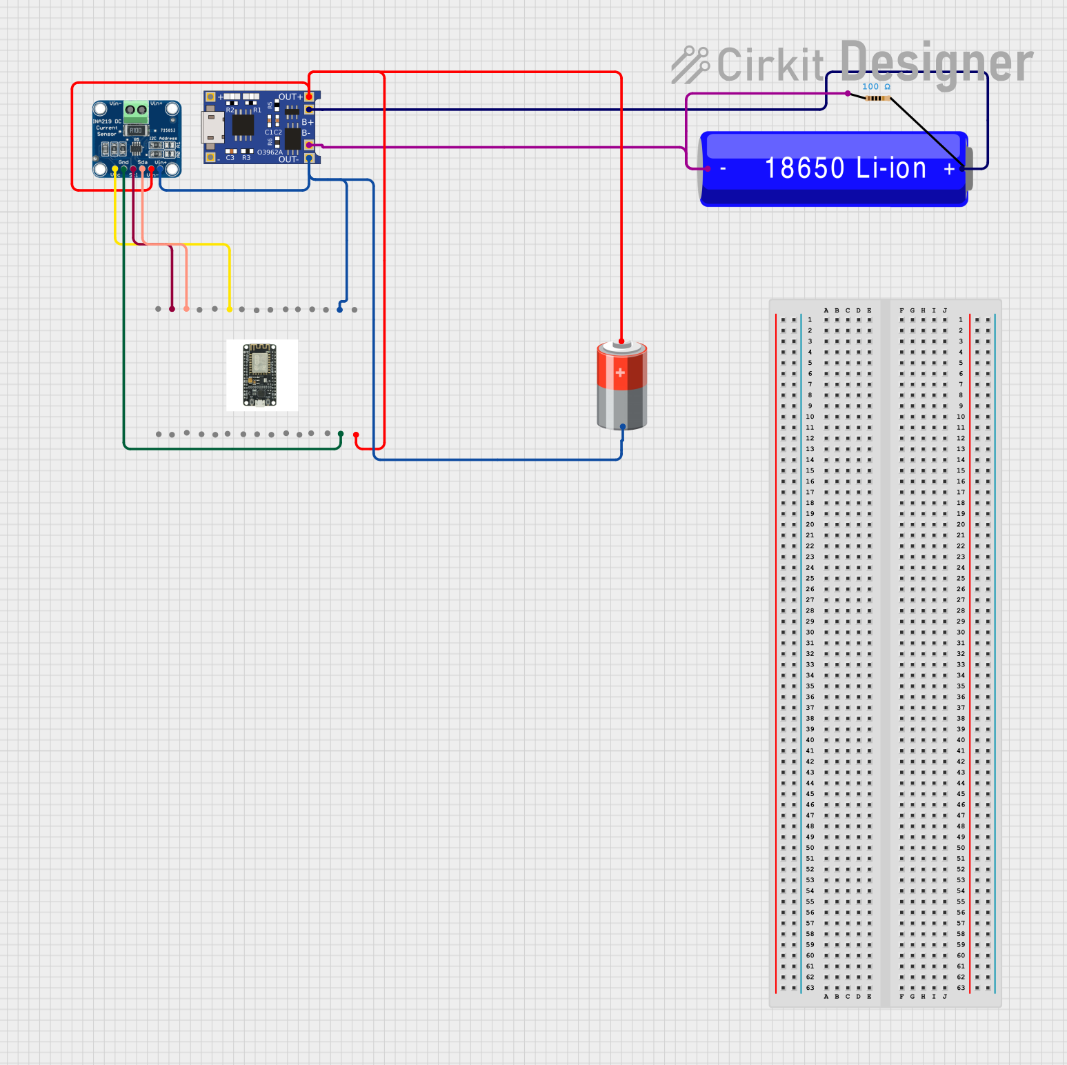
Circuit Documentation
Summary
This circuit is designed to monitor the voltage and current of a battery using an ESP8266 NodeMCU microcontroller and an INA219 current sensor. The circuit also includes a TP4056 battery charger module and a 18650 Li-ion battery. The ESP8266 NodeMCU reads the battery voltage and calculates the battery percentage, while the INA219 sensor measures the current and voltage of the battery. The TP4056 module is used to charge the 18650 Li-ion battery.
Component List
ESP8266 NodeMCU
- Description: A low-cost Wi-Fi microcontroller with multiple GPIO pins.
- Pins: D0, D1, D2, D3, D4, 3V3, GND, D5, D6, D7, D8, RX, TX, A0, RSV, SD3, SD2, SD1, CMD, SD0, CLK, EN, RST, VIN
18650 Li-ion Battery
- Description: A rechargeable lithium-ion battery.
- Pins: -, +
TP4056
- Description: A lithium battery charger module with overcharge protection.
- Pins: OUT-, B-, B+, OUT+, IN-, IN+
Resistor
- Description: A passive electrical component with a resistance of 100 Ohms.
- Pins: pin1, pin2
- Properties:
- Resistance: 100 Ohms
5V Battery
- Description: A 5V power source.
- Pins: +, -
INA219
- Description: A current sensor module that can measure both current and voltage.
- Pins: VCC, GND, SCL, SDA, VIN -, VIN +
Wiring Details
ESP8266 NodeMCU
- D1 is connected to SCL of INA219.
- D2 is connected to SDA of INA219.
- 3V3 is connected to VCC of INA219.
- GND is connected to GND of INA219, OUT- of TP4056, and VIN + of 5V Battery.
- VIN is connected to OUT+ of TP4056 and VIN - of INA219.
18650 Li-ion Battery
- - is connected to B- of TP4056 and pin1 of Resistor.
- + is connected to B+ of TP4056.
TP4056
- OUT- is connected to GND of ESP8266 NodeMCU and VIN + of INA219.
- OUT+ is connected to VIN of ESP8266 NodeMCU and VIN - of INA219.
- B- is connected to - of 18650 Li-ion Battery and pin1 of Resistor.
- B+ is connected to + of 18650 Li-ion Battery.
Resistor
- pin1 is connected to - of 18650 Li-ion Battery and B- of TP4056.
- pin2 is not connected in this circuit.
5V Battery
- - is connected to GND of ESP8266 NodeMCU, OUT- of TP4056, and VIN + of INA219.
- + is connected to VIN - of INA219 and OUT+ of TP4056.
INA219
- SCL is connected to D1 of ESP8266 NodeMCU.
- SDA is connected to D2 of ESP8266 NodeMCU.
- VCC is connected to 3V3 of ESP8266 NodeMCU.
- GND is connected to GND of ESP8266 NodeMCU.
- VIN - is connected to + of 5V Battery and OUT+ of TP4056.
- VIN + is connected to - of 5V Battery and OUT- of TP4056.
Documented Code
ESP8266 NodeMCU Code
// Define constants for voltage divider and battery
const float R1 = 100000.0; // Resistor R1 value (in ohms)
const float R2 = 100000.0; // Resistor R2 value (in ohms)
const float ADC_MAX = 1023.0; // Maximum ADC value for NodeMCU (10-bit ADC)
const float VREF = 3.3; // Reference voltage for NodeMCU ADC (in volts)
const float MAX_BATTERY_VOLTAGE = 4.2; // Fully charged battery voltage (in volts)
const float MIN_BATTERY_VOLTAGE = 3.0; // Minimum battery voltage (in volts)

// Variables for calculations
float adcValue = 0; // ADC reading
float batteryVoltage = 0; // Calculated battery voltage
float batteryPercentage = 0; // Calculated battery percentage

void setup() {
  Serial.begin(115200); // Start serial communication
}

void loop() {
  // Read ADC value from pin A0
  adcValue = analogRead(A0);

  // Calculate battery voltage based on voltage divider ratio
  batteryVoltage = (adcValue / ADC_MAX) * VREF * ((R1 + R2) / R2);

  // Calculate battery percentage
  batteryPercentage = ((batteryVoltage - MIN_BATTERY_VOLTAGE) /
                       (MAX_BATTERY_VOLTAGE - MIN_BATTERY_VOLTAGE)) * 100;

  // Limit percentage to 0-100%
  if (batteryPercentage > 100) {
    batteryPercentage = 100;
  } else if (batteryPercentage < 0) {
    batteryPercentage = 0;
  }

  // Print results to serial monitor
  Serial.print("ADC Value: ");
  Serial.print(adcValue);
  Serial.print(" | Battery Voltage: ");
  Serial.print(batteryVoltage, 2); // Print with 2 decimal places
  Serial.print(" V | Battery Percentage: ");
  Serial.print(batteryPercentage, 1); // Print with 1 decimal place
  Serial.println(" %");

  // Delay for readability (1 second)
  delay(1000);
}
INA219 Code
#include <Wire.h>
#include <Adafruit_INA219.h>

Adafruit_INA219 ina219;

void setup() {
  Serial.begin(115200);
  if (!ina219.begin()) {
    Serial.println("Failed to find INA219 chip");
    while (1);
  }
  Serial.println("INA219 Initialized");
}

void loop() {
  float current_mA = ina219.getCurrent_mA(); // Read current in mA
  float voltage = ina219.getBusVoltage_V() + (ina219.getShuntVoltage_mV() / 1000); // Battery voltage

  Serial.print("Current: ");
  Serial.print(current_mA);
  Serial.print(" mA | Voltage: ");
  Serial.print(voltage);
  Serial.println(" V");

  delay(1000);
}