
Arduino Mega 2560 Bluetooth-Controlled Robotic Car with L298N Motor Driver
View and Edit Project In Cirkit Designer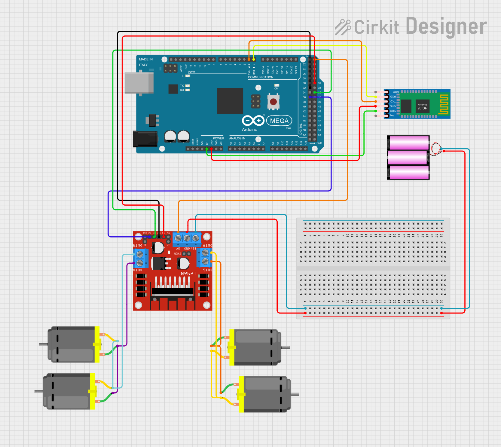
Circuit Documentation
Summary
This circuit is designed to control four DC motors using an Arduino Mega 2560 microcontroller and an L298N DC motor driver. The circuit also includes an HC-05 Bluetooth module for wireless communication. The power supply for the circuit is provided by a 12V battery.
Component List
HC-05 Bluetooth Module
- Description: A Bluetooth module used for wireless communication.
- Pins: Key, VCC, TXD, RXD, State, GND
L298N DC Motor Driver
- Description: A dual H-Bridge motor driver that allows control of the speed and direction of two DC motors.
- Pins: OUT1, OUT2, 12V, GND, 5V, OUT3, OUT4, 5V-ENA-JMP-I, 5V-ENA-JMP-O, +5V-J1, +5V-J2, ENA, IN1, IN2, IN3, IN4, ENB
Battery 12V
- Description: A 12V battery used to power the motor driver and motors.
- Pins: +, -
DC Motor
- Description: A DC motor used for driving mechanical components.
- Pins: pin 1, pin 2
Arduino Mega 2560
- Description: A microcontroller board based on the ATmega2560.
- Pins: IOREF, RESET, 3V3, 5V, GND, VIN, A0-A15, D0-D53, AREF, SDA, SCL
Wiring Details
HC-05 Bluetooth Module
- VCC connected to 5V of Arduino Mega 2560
- GND connected to GND of Arduino Mega 2560
- RXD connected to D0 RX0 of Arduino Mega 2560
- TXD connected to D1 TX0 of Arduino Mega 2560
L298N DC Motor Driver
- GND connected to - of Battery 12V
- 12V connected to + of Battery 12V
- 5V connected to 5V of Arduino Mega 2560
- IN1 connected to D31 of Arduino Mega 2560
- IN2 connected to D32 of Arduino Mega 2560
- IN3 connected to D35 of Arduino Mega 2560
- IN4 connected to D36 of Arduino Mega 2560
- OUT1 connected to pin 1 of DC Motor 1 and pin 1 of DC Motor 2
- OUT2 connected to pin 2 of DC Motor 1 and pin 2 of DC Motor 2
- OUT3 connected to pin 2 of DC Motor 3 and pin 2 of DC Motor 4
- OUT4 connected to pin 1 of DC Motor 3 and pin 1 of DC Motor 4
Battery 12V
- + connected to 12V of L298N DC Motor Driver
- - connected to GND of L298N DC Motor Driver
DC Motor 1
- pin 1 connected to OUT1 of L298N DC Motor Driver
- pin 2 connected to OUT2 of L298N DC Motor Driver
DC Motor 2
- pin 1 connected to OUT1 of L298N DC Motor Driver
- pin 2 connected to OUT2 of L298N DC Motor Driver
DC Motor 3
- pin 1 connected to OUT4 of L298N DC Motor Driver
- pin 2 connected to OUT3 of L298N DC Motor Driver
DC Motor 4
- pin 1 connected to OUT4 of L298N DC Motor Driver
- pin 2 connected to OUT3 of L298N DC Motor Driver
Documented Code
const int motorPins[4] = {31, 32, 35, 36}; // Motor pins
char val;

void setup() {
  for (int i = 0; i < 4; i++) {
    pinMode(motorPins[i], OUTPUT);
  }
  Serial.begin(9600);
}

void stopMotors() {
  for (int i = 0; i < 4; i++) {
    digitalWrite(motorPins[i], LOW);
  }
}

void moveMotors(int m1aState, int m1bState, int m2aState, int m2bState) {
  digitalWrite(motorPins[0], m1aState);
  digitalWrite(motorPins[1], m1bState);
  digitalWrite(motorPins[2], m2aState);
  digitalWrite(motorPins[3], m2bState);
}

void moveMotorsPWM(int m1aSpeed, int m1bSpeed, int m2aSpeed, int m2bSpeed) {
  analogWrite(motorPins[0], m1aSpeed);
  analogWrite(motorPins[1], m1bSpeed);
  analogWrite(motorPins[2], m2aSpeed);
  analogWrite(motorPins[3], m2bSpeed);
}

void loop() {
  while (Serial.available() > 0) {
    val = Serial.read();
    Serial.println(val);

    switch (val) {
      case 'B': // Forward
        moveMotors(HIGH, LOW, HIGH, LOW);
        break;

      case 'F': // Backward
        moveMotors(LOW, HIGH, LOW, HIGH);
        break;

      case 'R': // Left
        moveMotors(LOW, LOW, HIGH, LOW);
        break;

      case 'L': // Right
        moveMotors(HIGH, LOW, LOW, LOW);
        break;

      case 'S': // Stop
        stopMotors();
        break;

      case 'I': // Forward Right
        moveMotorsPWM(255, 0, 128, 0); // Left motor full speed, right motor half speed
        break;

      case 'G': // Forward Left
        moveMotorsPWM(128, 0, 255, 0); // Left motor half speed, right motor full speed
        break;

      case 'J': // Backward Right
        moveMotorsPWM(0, 255, 0, 128); // Left motor full speed reverse, right motor half speed reverse
        break;

      case 'H': // Backward Left
        moveMotorsPWM(0, 128, 0, 255); // Left motor half speed reverse, right motor full speed reverse
        break;

      default: // Invalid command
        stopMotors();
        break;
    }
  }
}
This code is designed to control the four DC motors connected to the L298N motor driver via the Arduino Mega 2560. The motors can be controlled using commands received via the HC-05 Bluetooth module. The commands allow the motors to move forward, backward, left, right, and stop, as well as perform more complex maneuvers like forward right, forward left, backward right, and backward left.