Cirkit Designer
Your all-in-one circuit design IDE
Home /
Project Documentation
Arduino Mega 2560 Controlled Dual Stepper Motor System with VL53L1X Distance Sensor and Relay Switching
Circuit Documentation
Summary
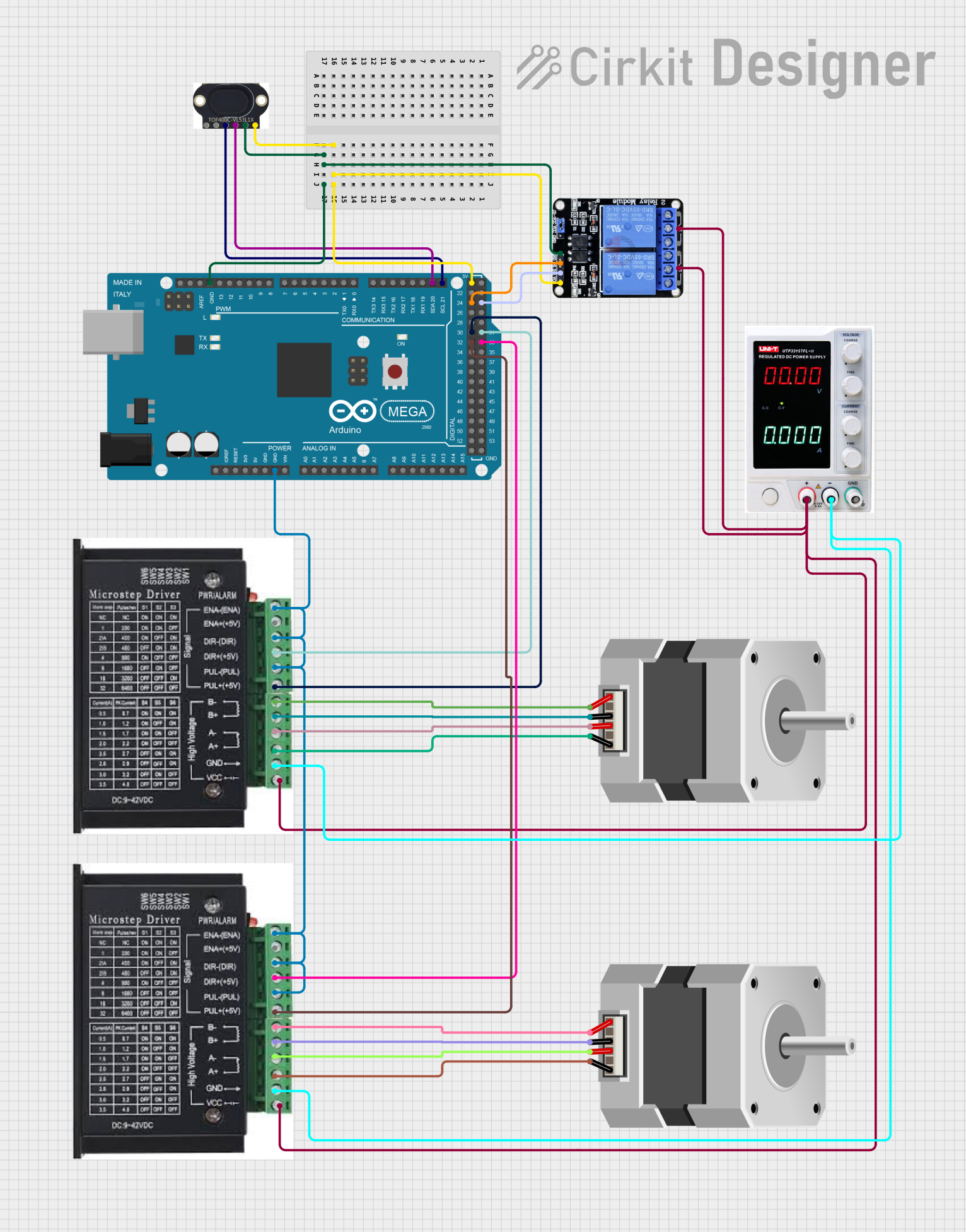
This circuit integrates an Arduino Mega 2560 with a VL53L1X sensor, two stepper drivers connected to two bipolar stepper motors, a two-channel 5V relay, and a power supply. The Arduino Mega 2560 serves as the central controller, interfacing with the VL53L1X sensor via I2C communication and controlling the stepper drivers and relay module through its GPIO pins. The power supply provides the necessary voltage and current to drive the stepper motors and relay module.
Component List
Arduino Mega 2560
- Microcontroller board based on the ATmega2560
- Offers numerous digital input/output pins, including PWM outputs, and analog inputs
- Provides I2C, SPI, and UART communication interfaces
VL53L1X Time-of-Flight Sensor
- A laser-ranging module that provides accurate distance measurements
- Interfaces with the Arduino via I2C communication
Stepper Drivers (2x)
- Modules that control bipolar stepper motors
- Provide inputs for step, direction, and enable signals
Bipolar Stepper Motors (2x)
- Motors that can be precisely controlled by changing the current direction through their coils
- Driven by the stepper drivers
Two Channel Relay 5V
- A module with two independent relay channels
- Can be used to control high power devices with Arduino's low power signals
Power Supply
- Provides the required voltage and current to the stepper drivers and relay module
Wiring Details
Arduino Mega 2560
GNDconnected to the ground pins of the VL53L1X, stepper drivers, and relay moduleD21/SCLconnected to theSCLpin of the VL53L1XD20/SDAconnected to theSDApin of the VL53L1X5Vconnected to theVINpin of the VL53L1X andVCCof the relay moduleD32andD30connected to thePUL +pins of the stepper driversD33andD31connected to theDIR+pins of the stepper driversD24andD25connected to theIN1andIN2pins of the relay module
VL53L1X Time-of-Flight Sensor
SCLandSDAconnected to the corresponding I2C pins on the Arduino Mega 2560GNDconnected to the Arduino's groundVINconnected to the Arduino's 5V output
Stepper Drivers
ENA,DIR-, andPUL-connected to the groundPUL +connected toD32andD30on the Arduino for pulse controlDIR+connected toD33andD31on the Arduino for direction controlGNDconnected to the negative terminal of the power supplyVCCconnected to the positive terminal of the power supply
Bipolar Stepper Motors
A,B,C,Dconnected to the correspondingA+,A-,B+,B-pins on the stepper drivers
Two Channel Relay 5V
GNDconnected to the Arduino's groundVCCconnected to the Arduino's 5V outputIN1andIN2connected toD24andD25on the ArduinoC1andC2connected to the positive terminal of the power supply
Power Supply
+connected to theVCCof the stepper drivers andC1,C2of the relay module-connected to theGNDof the stepper drivers
Documented Code
Arduino Mega 2560 - sketch.ino
void setup() {
  // put your setup code here, to run once:

}

void loop() {
  // put your main code here, to run repeatedly:

}
Arduino Mega 2560 - documentation.txt
(No additional documentation provided)
This concludes the documentation for the given circuit. The code provided is a template and does not contain any functional implementation. It should be populated with the necessary setup and loop code to control the components as per the circuit's requirements.