
Arduino Mega 2560 Based Sensor Monitoring and Display System
View and Edit Project In Cirkit Designer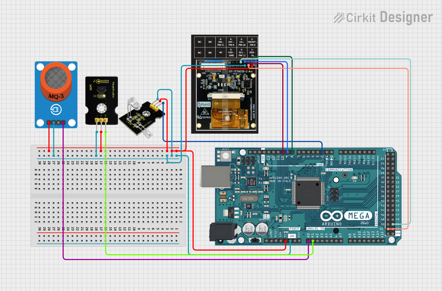
Circuit Documentation
Summary of the Circuit
This circuit integrates an Arduino Mega 2560 microcontroller with several peripheral devices: an MQ-3 alcohol sensor breakout, a pulse meter, a linear temperature sensor, and a TFT display. The Arduino Mega 2560 serves as the central processing unit, interfacing with the sensors to collect data and with the display to provide visual output. The circuit is designed to monitor alcohol levels, pulse rate, and temperature, displaying this information on the TFT screen.
Component List
Arduino Mega 2560
- Description: A microcontroller board based on the ATmega2560.
- Pins: Multiple digital and analog I/O pins, power supply pins (3.3V, 5V), and ground pins (GND).
MQ-3 Alcohol Sensor Breakout
- Description: A breakout board for the MQ-3 alcohol sensor.
- Pins: VCC, GND, Digital Output (DO), Analog Output (AO).
Pulse Meter
- Description: A sensor for measuring the pulse rate.
- Pins: GND, Signal (S), 5V.
Linear Temperature Sensor
- Description: A sensor for measuring temperature linearly related to the Celsius scale.
- Pins: Signal (S), 5V, GND.
TFT Display
- Description: A thin-film-transistor liquid-crystal display for visual output.
- Pins: Multiple pins for interfacing with the microcontroller.
Wiring Details
Arduino Mega 2560
- 5V: Connected to the 5V power supply pins of the Pulse Meter, Linear Temperature Sensor, MQ-3 Breakout, and pin 1 of the TFT Display.
- GND: Connected to the ground pins of the Pulse Meter, Linear Temperature Sensor, MQ-3 Breakout, and pin 5 of the TFT Display.
- A0: Connected to the Analog Output (AO) of the MQ-3 Breakout.
- A1: Connected to the Signal (S) of the Linear Temperature Sensor.
- D2 PWM: Connected to the Signal (S) of the Pulse Meter.
- D8 PWM: Connected to pin 2 of the TFT Display.
- D9 PWM: Connected to pin 6 of the TFT Display.
- D10 PWM: Connected to pin 4 of the TFT Display.
- D52: Connected to pin 3 of the TFT Display.
- D51: Connected to pin 8 of the TFT Display.
MQ-3 Alcohol Sensor Breakout
- VCC: Connected to the 5V output from the Arduino Mega 2560.
- GND: Connected to the ground on the Arduino Mega 2560.
- AO: Connected to the A0 pin on the Arduino Mega 2560.
Pulse Meter
- 5V: Connected to the 5V output from the Arduino Mega 2560.
- GND: Connected to the ground on the Arduino Mega 2560.
- S: Connected to the D2 PWM pin on the Arduino Mega 2560.
Linear Temperature Sensor
- 5V: Connected to the 5V output from the Arduino Mega 2560.
- GND: Connected to the ground on the Arduino Mega 2560.
- S: Connected to the A1 pin on the Arduino Mega 2560.
TFT Display
- Pin 1: Connected to the 5V output from the Arduino Mega 2560.
- Pin 2: Connected to the D8 PWM pin on the Arduino Mega 2560.
- Pin 3: Connected to the D52 pin on the Arduino Mega 2560.
- Pin 4: Connected to the D10 PWM pin on the Arduino Mega 2560.
- Pin 5: Connected to the ground on the Arduino Mega 2560.
- Pin 6: Connected to the D9 PWM pin on the Arduino Mega 2560.
- Pin 8: Connected to the D51 pin on the Arduino Mega 2560.
Documented Code
Arduino Mega 2560
File: sketch.ino
void setup() {
  // put your setup code here, to run once:

}

void loop() {
  // put your main code here, to run repeatedly:

}
File: documentation.txt
(No additional documentation provided for the code)
This concludes the documentation for the given circuit. The circuit is designed to be modular, allowing for easy integration or removal of components. The code provided is a template and should be expanded to initialize and read from the sensors, process the data, and display the results on the TFT screen.