
ESP32-Based LoRa Communication System with Alert Notifications
View and Edit Project In Cirkit Designer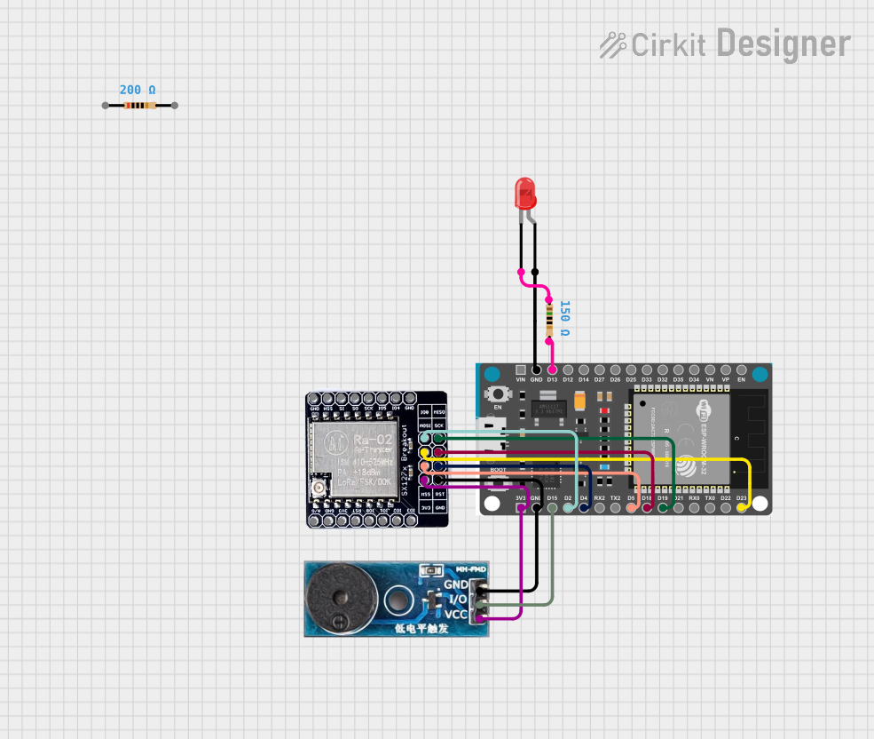
Circuit Documentation
Summary of the Circuit
The circuit in question appears to be a communication system utilizing an ESP32 Devkit V1 microcontroller as the central processing unit, interfaced with a LORA_RA02 module for long-range communication. Additionally, the circuit includes a buzzer module for audio signaling and an LED indicator with a current-limiting resistor. The ESP32 Devkit V1 provides power to the LORA_RA02 and the buzzer module, and it controls the buzzer and LED through its GPIO pins. The LORA_RA02 is connected to the ESP32 via SPI and additional control lines for communication purposes.
Component List
Resistor (200 Ohms)
- Description: A passive two-terminal electrical component that implements electrical resistance as a circuit element.
- Purpose: Typically used for current limiting or voltage dropping.
Resistor (150 Ohms)
- Description: Another passive two-terminal electrical component with a different resistance value.
- Purpose: Used for current limiting, often for an LED to ensure it operates within its current specifications.
Buzzer Module
- Description: An audio signaling device that can be used to alert users or provide feedback.
- Purpose: In this circuit, it is likely used to provide audible feedback or alerts.
ESP32 Devkit V1
- Description: A microcontroller with Wi-Fi and Bluetooth capabilities, suitable for a variety of applications in the IoT domain.
- Purpose: Acts as the central processing unit of the circuit, controlling the LORA module, buzzer, and LED.
LORA_RA02
- Description: A long-range communication module based on LoRa technology, suitable for low-power applications.
- Purpose: Provides long-range communication capabilities to the circuit.
LED: Two Pin (red)
- Description: A basic light-emitting diode that emits red light when powered.
- Purpose: Serves as an indicator light in the circuit.
Wiring Details
Resistor (200 Ohms)
- Connections: Not connected in the provided net list.
Resistor (150 Ohms)
- Connections:
- One side connected to the ESP32 Devkit V1's GPIO pin D13.
- The other side connected to the anode of the LED.
Buzzer Module
- Connections:
- GND pin connected to the ESP32 Devkit V1's GND.
- Vcc pin connected to the ESP32 Devkit V1's 3V3.
- I/O pin connected to the ESP32 Devkit V1's GPIO pin D15.
ESP32 Devkit V1
- Connections:
- 3V3 pin providing power to the LORA_RA02 and Buzzer Module.
- GND pin connected to the ground of LORA_RA02, Buzzer Module, and LED.
- GPIO pins D15, D2, D4, D5, D18, D19, D23, and D13 are used for controlling the Buzzer Module, LORA_RA02, and LED.
LORA_RA02
- Connections:
- 3V3 and GND for power.
- RST, IO_0, NSS, SCK, MISO, and MOSI pins connected to corresponding GPIO pins on the ESP32 Devkit V1 for SPI communication and control.
LED: Two Pin (red)
- Connections:
- Anode connected to the 150 Ohm resistor.
- Cathode connected to the ground.
Documented Code
There is no code provided for the microcontroller. Typically, the code would be documented here, including setup routines, main loop, and functions for handling the communication with the LORA module, controlling the buzzer, and managing the LED state. Since no code is available, this section remains empty.