
Arduino-Controlled Temperature-Responsive Fan with OLED Display
View and Edit Project In Cirkit Designer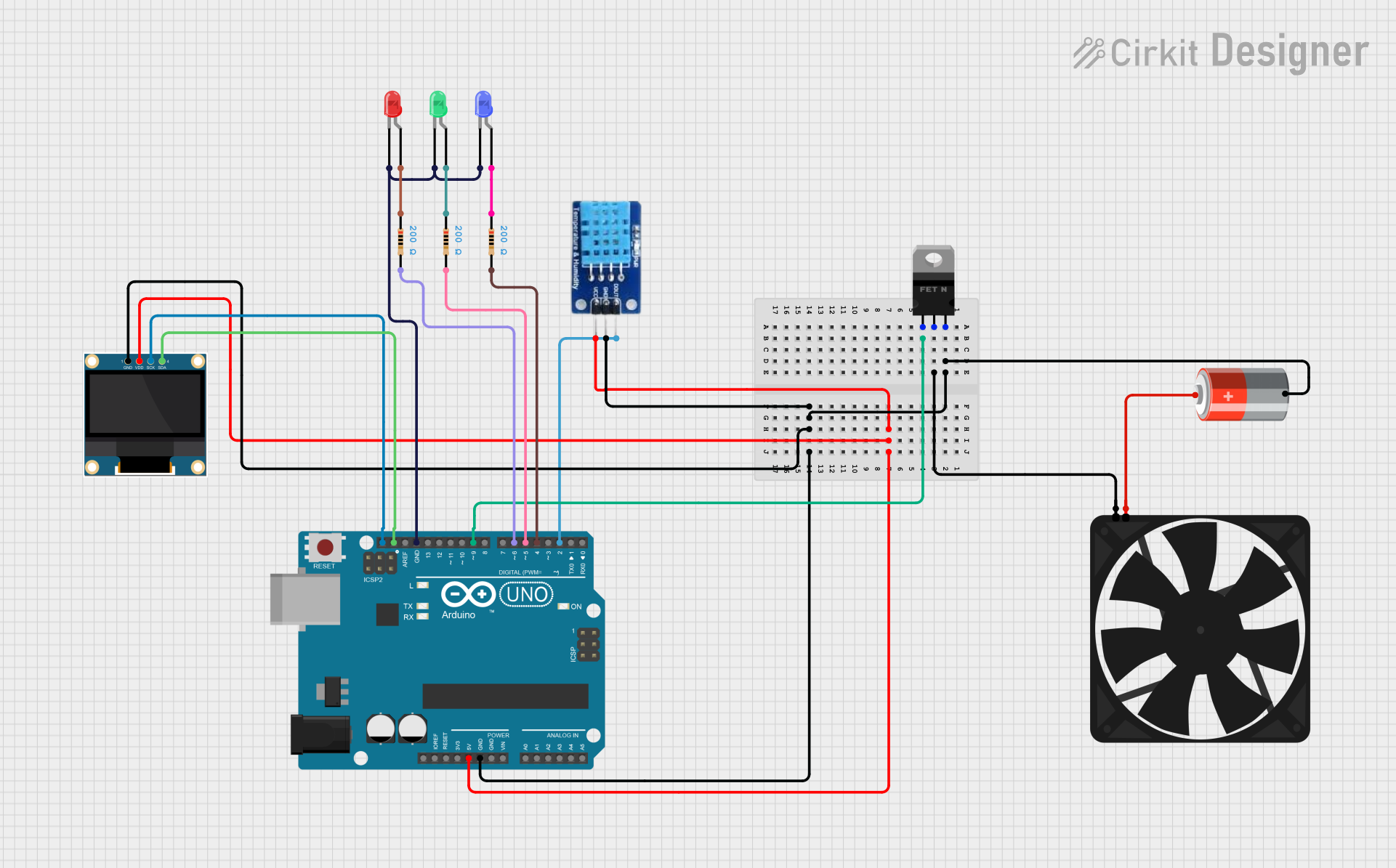
Circuit Documentation
Summary
This circuit is designed to control a fan's speed based on temperature readings from a DHT11 sensor. The fan is powered by a 5V battery and its speed is controlled by an nMOS transistor (MOSFET) which is driven by an Arduino UNO microcontroller. The temperature is displayed on a 0.96" OLED screen. The circuit also includes three LEDs (red, green, and blue) each with a current-limiting resistor to indicate different states or conditions as programmed in the Arduino.
Component List
nMOS Transistor (MOSFET)
- Description: A three-terminal device used for switching electronic signals.
- Pins: gate, drain, source
5V Battery
- Description: Provides the power supply for the circuit.
- Pins: + (positive), - (negative)
Arduino UNO
- Description: A microcontroller board based on the ATmega328P.
- Pins: UNUSED, IOREF, Reset, 3.3V, 5V, GND, Vin, A0-A5, SCL, SDA, AREF, D0-D13
Fan
- Description: An electric device powered by the 5V supply to circulate air.
- Pins: GND, 5V
0.96" OLED
- Description: A small display for visual output from the Arduino.
- Pins: GND, VDD, SCK, SDA
DHT11
- Description: A basic, ultra low-cost digital temperature and humidity sensor.
- Pins: DATA, GND, VCC
LEDs: Two Pin (red, green, blue)
- Description: Light-emitting diodes used as indicators.
- Pins: cathode, anode
Resistors (200 Ohms)
- Description: Used to limit current to the LEDs.
- Pins: pin1, pin2
- Properties: Resistance: 200 Ohms
Wiring Details
nMOS Transistor (MOSFET)
- Gate: Connected to Arduino UNO D9
- Drain: Connected to Fan GND
- Source: Connected to GND net (Arduino UNO GND, DHT11 GND, 5V Battery -, 0.96" OLED GND)
5V Battery
- + (positive): Connected to Fan 5V
- - (negative): Connected to GND net
Arduino UNO
- 5V: Connected to DHT11 VCC and 0.96" OLED VDD
- GND: Connected to GND net
- D9: Connected to nMOS Transistor gate
- D2: Connected to DHT11 DATA
- D4, D5, D6: Connected to respective resistors for LEDs
- SCL: Connected to 0.96" OLED SCK
- SDA: Connected to 0.96" OLED SDA
Fan
- 5V: Connected to 5V Battery +
- GND: Connected to nMOS Transistor drain
0.96" OLED
- VDD: Connected to Arduino UNO 5V
- GND: Connected to GND net
- SCK: Connected to Arduino UNO SCL
- SDA: Connected to Arduino UNO SDA
DHT11
- VCC: Connected to Arduino UNO 5V
- GND: Connected to GND net
- DATA: Connected to Arduino UNO D2
LEDs (red, green, blue)
- Cathode (all): Connected to GND net
- Anode (red): Connected to resistor (200 Ohms) linked to Arduino UNO D6
- Anode (green): Connected to resistor (200 Ohms) linked to Arduino UNO D5
- Anode (blue): Connected to resistor (200 Ohms) linked to Arduino UNO D4
Resistors (200 Ohms)
- Pin1 (red LED): Connected to red LED anode
- Pin2 (red LED): Connected to Arduino UNO D6
- Pin1 (green LED): Connected to green LED anode
- Pin2 (green LED): Connected to Arduino UNO D5
- Pin1 (blue LED): Connected to blue LED anode
- Pin2 (blue LED): Connected to Arduino UNO D4
Documented Code
/*
 * This Arduino Sketch controls a fan's speed based on temperature readings
 * from a DHT11 sensor. The fan speed is varied using a MOSFET controlled
 * by the Arduino. The fan speed increases when the temperature is above
 * 35°C, runs at normal speed between 25°C and 35°C, and decreases when
 * the temperature is below 25°C. The temperature is also displayed on an
 * OLED screen.
 */

#include <DHT.h>
#include <Wire.h>
#include <Adafruit_GFX.h>
#include <Adafruit_SSD1306.h>

#define DHTPIN 2          // Define the pin connected to the DHT11 data pin
#define DHTTYPE DHT11     // Define the type of DHT sensor
#define FAN_PIN 9         // Define the pin controlling the MOSFET gate
#define SCREEN_WIDTH 128  // OLED display width
#define SCREEN_HEIGHT 64  // OLED display height

DHT dht(DHTPIN, DHTTYPE);  // Initialize the DHT sensor
Adafruit_SSD1306 display(SCREEN_WIDTH, SCREEN_HEIGHT, &Wire, -1);  // Initialize the OLED display

void setup() {
  pinMode(FAN_PIN, OUTPUT);  // Set the fan control pin as an output
  dht.begin();               // Start the DHT sensor
  if(!display.begin(SSD1306_SWITCHAPVCC, 0x3C)) {  // Initialize the OLED display
    for(;;);  // Infinite loop if display initialization fails
  }
  display.clearDisplay();  // Clear the display buffer
  display.setTextSize(1);  // Set text size
  display.setTextColor(SSD1306_WHITE);  // Set text color
}

void loop() {
  float temp = dht.readTemperature();  // Read temperature from DHT sensor
  if (isnan(temp)) {  // Check if the reading failed
    return;  // Do nothing if the reading failed
  }
  display.clearDisplay();  // Clear the display buffer
  display.setCursor(0, 0);  // Set cursor to top-left corner
  display.print("Temp: ");  // Display the text "Temp: "
  display.print(temp);      // Display the temperature value
  display.print(" C");      // Display the text " C" for Celsius
  display.display();        // Update the display with new data

  // Control the fan speed based on the temperature
  if (temp > 35) {
    analogWrite(FAN_PIN, 255);  // Set fan to maximum speed
  } else if (temp >= 25) {
    analogWrite(FAN_PIN, 128);  // Set fan to medium speed
  } else {
    analogWrite(FAN_PIN, 64);   // Set fan to low speed
  }
  delay(2000);  // Wait for 2 seconds before reading the temperature again
}
This code is saved as sketch.ino and is intended to be uploaded to the Arduino UNO microcontroller. It includes the necessary libraries for the DHT11 sensor and the OLED display, defines the pin connections, initializes the devices, and contains the main program logic to read the temperature, display it on the OLED, and control the fan speed accordingly.