
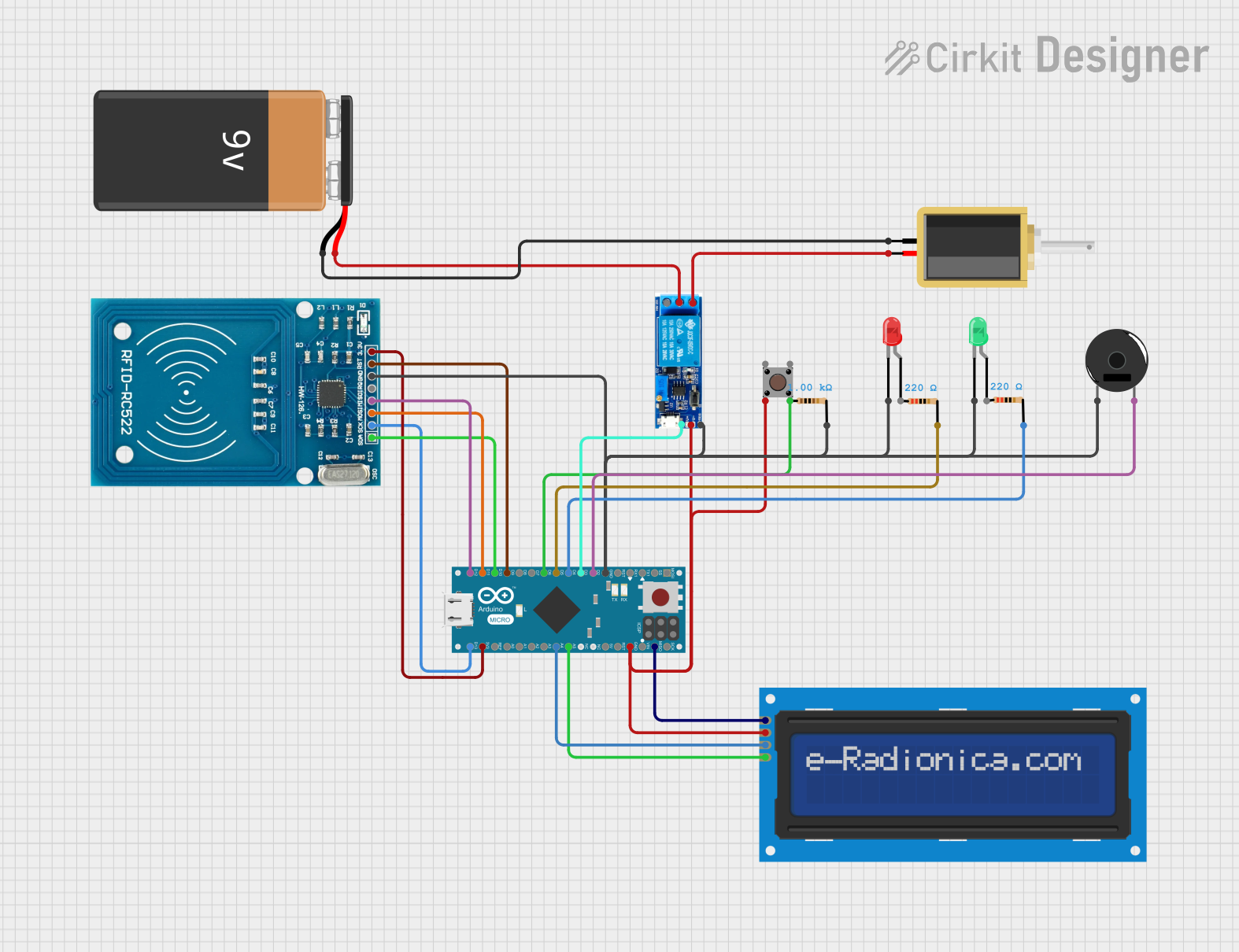
RFID Door Lock System Documentation
Summary
The RFID Door Lock System is designed to control access through a door using RFID technology. The system uses an Arduino Micro as the central processing unit, interfacing with an RFID-RC522 module to read RFID tags. When a valid RFID tag is presented, the system activates a solenoid lock, allowing access. The system provides visual feedback through red and green LEDs and audible feedback with a piezo buzzer. An LCD screen displays the system status. A pushbutton is included to manually override the system and unlock the door. The system is powered by a 9V battery and uses a relay module to control the higher voltage required by the solenoid.
Component List
- RFID-RC522: An RFID reader module for reading RFID tags.
- Solenoid: An electromagnetic actuator used as a locking mechanism.
- LED (Red): A red LED used to indicate access denial or error states.
- LED (Green): A green LED used to indicate access granted.
- Piezo Buzzer: An electronic device that emits a tone when activated, used for audible feedback.
- Pushbutton: A manual switch to override the system and unlock the door.
- Resistors: Electrical components used to limit current through LEDs and provide pull-up/down functionalities.
- Relay Module (5V-30V): An electrically operated switch that allows the control of a high voltage circuit by a low voltage signal from the Arduino.
- Arduino Micro (Rev3): A microcontroller board based on the ATmega32U4, used as the main controller for the system.
- LCD Screen (16x2 I2C): A liquid crystal display that shows the system status and messages.
- 9V Battery: The power source for the system.
Wiring Details
RFID-RC522
- VCC (3.3V): Connected to the 3.3V output on the Arduino Micro.
- RST: Connected to digital pin 9 on the Arduino Micro.
- GND: Connected to the ground (GND) on the Arduino Micro.
- IRQ: Not connected.
- MISO: Connected to MISO on the Arduino Micro.
- MOSI: Connected to MOSI on the Arduino Micro.
- SCK: Connected to digital pin 13 on the Arduino Micro.
- SDA: Connected to digital pin 10 on the Arduino Micro.
Solenoid
- Pin1: Connected to the normally open contact of the relay module.
- Pin2: Connected to the positive terminal of the 9V battery.
LED (Red)
- Cathode: Connected to the ground (GND) through a 220 Ohm resistor.
- Anode: Connected to digital pin 5 on the Arduino Micro.
LED (Green)
- Cathode: Connected to the ground (GND) through a 220 Ohm resistor.
- Anode: Connected to digital pin 4 on the Arduino Micro.
Piezo Buzzer
- Pin 1: Connected to the ground (GND).
- Pin 2: Connected to digital pin 2 on the Arduino Micro.
Pushbutton
- Pin 3 (out): Not connected.
- Pin 4 (out): Connected to digital pin 6 on the Arduino Micro.
- Pin 1 (in): Connected to the ground (GND).
- Pin 2 (in): Connected to the ground (GND).
Resistor (220 Ohms)
- Pin1: Connected to the anode of the red LED.
- Pin2: Connected to digital pin 5 on the Arduino Micro.
Resistor (1000 Ohms)
- Pin1: Not connected.
- Pin2: Connected to the ground (GND).
Resistor (220 Ohms)
- Pin1: Connected to the anode of the green LED.
- Pin2: Connected to digital pin 4 on the Arduino Micro.
Relay Module (5V-30V)
- Common Contact: Connected to the positive terminal of the 9V battery.
- Normally Open: Connected to pin 1 of the Solenoid.
- Normally Closed: Not connected.
- Trigger: Connected to digital pin 3 on the Arduino Micro.
- V-: Connected to the ground (GND).
- V+: Connected to the 5V output on the Arduino Micro.
LCD Screen (16x2 I2C)
- SCL: Connected to analog pin 5 on the Arduino Micro.
- SDA: Connected to analog pin 4 on the Arduino Micro.
- VCC: Connected to the 5V output on the Arduino Micro.
- GND: Connected to the ground (GND).
9V Battery
- (-): Connected to the ground (GND).
- (+): Connected to the common contact of the relay module and pin 2 of the Solenoid.
Documented Code
The code for the Arduino Micro is written in C++ and uses several libraries to interface with the RFID-RC522 module, the LCD screen, and to control the GPIO pins. The code is structured into two main functions: setup() and loop(). The setup() function initializes the serial communication, SPI bus, RFID reader, GPIO pins, and the LCD screen. The loop() function continuously checks for the presence of an RFID card, reads the card's UID, and compares it to a predefined valid UID. If the UID matches, it grants access by activating the solenoid lock, turning on the green LED, and sounding the buzzer. If the UID does not match, it denies access, activates the red LED, and sounds the buzzer in a different tone. The pushbutton provides a manual override to unlock the door.
#include <Wire.h>
#include <SPI.h>
#include <MFRC522.h>
#include <LiquidCrystal_I2C.h>

LiquidCrystal_I2C lcd(0x3F, 16, 2);

#define SS_PIN 10
#define RST_PIN 9
#define LED_G 4 //define green LED pin
#define LED_R 5 //define red LED
#define BUZZER 2 //buzzer pin
#define lock 3
MFRC522 mfrc522(SS_PIN, RST_PIN);   // Create MFRC522 instance.
int Btn = 6;

void setup()
{
  Serial.begin(9600);   // Initiate a serial communication
  SPI.begin();      // Initiate SPI bus
  mfrc522.PCD_Init();   // Initiate MFRC522
  pinMode(LED_G, OUTPUT);
  pinMode(LED_R, OUTPUT);
  pinMode(BUZZER, OUTPUT);
  noTone(BUZZER);
  pinMode(Btn, INPUT);
  pinMode(lock, OUTPUT);
  Serial.println("Place your card on reader...");
  Serial.println();
  lcd.begin();
  lcd.backlight();
  lcd.clear();
  lcd.setCursor(0,0); // column, row
  lcd.print(" Scan Your RFID ");
  lcd.setCursor(0,1); // column, row
  lcd.print("   Door Locked   ");
}

void loop()
{
  // Manual override button
  if (digitalRead(Btn) == HIGH)
  {
    // Unlock door sequence
  }

  // RFID card detection and validation
  if (!mfrc522.PICC_IsNewCardPresent())
  {
    return;
  }

  if (!mfrc522.PICC_ReadCardSerial())
  {
    return;
  }

  // Process the read UID and compare with authorized UID
  // Grant or deny access based on the UID
}
Note: The code provided above is a simplified version of the actual implementation. It includes the main structure and key functionalities. The full code includes additional logic for handling the RFID reading, access granting, and system feedback through LEDs and buzzer.