Cirkit Designer
Your all-in-one circuit design IDE
Home /
Project Documentation
Arduino Mega 2560-Based Smart Home Control System with LCD Display and Flame Sensor

Circuit Documentation
Summary
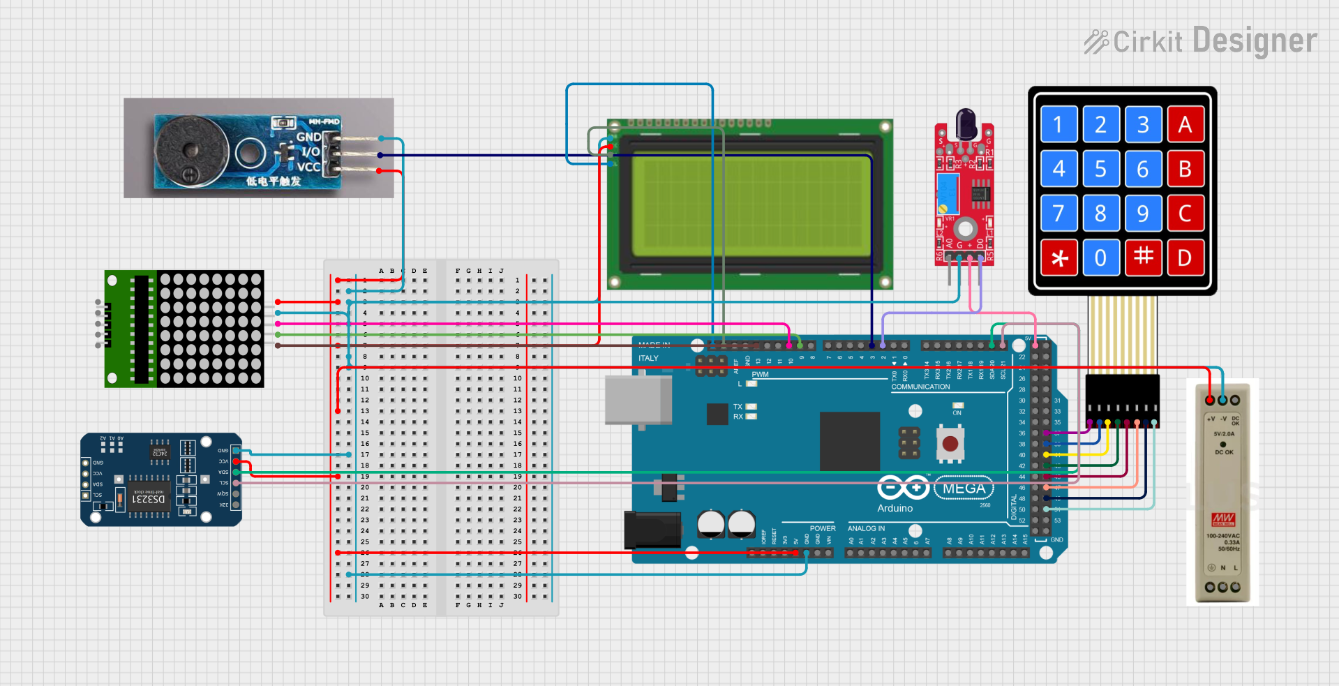
This document provides a detailed overview of a circuit that includes various components such as a 4x4 Membrane Matrix Keypad, an LCD display, a power supply unit, an Arduino Mega 2560, a real-time clock module, a passive buzzer, an 8x8 LED matrix, and a flame sensor. The circuit is designed to interface these components with the Arduino Mega 2560, which controls their operation through embedded code.
Component List
4X4 Membrane Matrix Keypad
- Description: A keypad with 4 rows and 4 columns, used for user input.
- Pins: R1, R2, R3, R4, C1, C2, C3, C4
Lcd 20x4 i2c
- Description: A 20x4 character LCD display with I2C interface.
- Pins: GND, 5v, SCA, SCL
5V PSU
- Description: A 5V power supply unit.
- Pins: 5V+, GND, 5V OK, PE, N, L
Arduino Mega 2560
- Description: A microcontroller board based on the ATmega2560.
- Pins: IOREF, RESET, 3V3, 5V, GND, VIN, A0-A15, D0-D53, PWM, AREF, SDA, SCL
DS3231 RTC
- Description: A real-time clock module.
- Pins: 32K, SQW, SCL, SDA, VCC, GND
Passive Buzzer Module
- Description: A module that produces sound when a voltage is applied.
- Pins: GND, I/O, VCC
8x8 Matrix
- Description: An 8x8 LED matrix display.
- Pins: vcc, DIN, clk, CS, Gnd, gnd, CLK
KY-026 Flame Sensor
- Description: A sensor module that detects flame.
- Pins: AO, GND, VCC, DO
Wiring Details
4X4 Membrane Matrix Keypad
- C4: Connected to Arduino Mega 2560 pin D51
- C3: Connected to Arduino Mega 2560 pin D49
- C2: Connected to Arduino Mega 2560 pin D47
- C1: Connected to Arduino Mega 2560 pin D45
- R4: Connected to Arduino Mega 2560 pin D43
- R3: Connected to Arduino Mega 2560 pin D41
- R2: Connected to Arduino Mega 2560 pin D39
- R1: Connected to Arduino Mega 2560 pin D37
Lcd 20x4 i2c
- GND: Connected to 5V PSU GND
- 5v: Connected to 5V PSU 5V+
- SCA: Connected to Arduino Mega 2560 SDA
- SCL: Connected to Arduino Mega 2560 SCL
5V PSU
- 5V+: Connected to Arduino Mega 2560 5V, Lcd 20x4 i2c 5v, DS3231 RTC VCC, Passive Buzzer Module VCC, 8x8 Matrix vcc
- GND: Connected to Arduino Mega 2560 GND, Lcd 20x4 i2c GND, DS3231 RTC GND, Passive Buzzer Module GND, 8x8 Matrix gnd, KY-026 Flame Sensor GND
Arduino Mega 2560
- 5V: Connected to 5V PSU 5V+
- GND: Connected to 5V PSU GND
- D21/SCL: Connected to DS3231 RTC SCL
- D20/SDA: Connected to DS3231 RTC SDA
- D2 PWM: Connected to KY-026 Flame Sensor DO
- D3 PWM: Connected to Passive Buzzer Module I/O
- D9 PWM: Connected to 8x8 Matrix CLK
- D10 PWM: Connected to 8x8 Matrix DIN
- D13 PWM: Connected to 8x8 Matrix CS
- SDA: Connected to Lcd 20x4 i2c SCA
- SCL: Connected to Lcd 20x4 i2c SCL
- D51: Connected to 4X4 Membrane Matrix Keypad C4
- D49: Connected to 4X4 Membrane Matrix Keypad C3
- D47: Connected to 4X4 Membrane Matrix Keypad C2
- D45: Connected to 4X4 Membrane Matrix Keypad C1
- D43: Connected to 4X4 Membrane Matrix Keypad R4
- D41: Connected to 4X4 Membrane Matrix Keypad R3
- D39: Connected to 4X4 Membrane Matrix Keypad R2
- D37: Connected to 4X4 Membrane Matrix Keypad R1
DS3231 RTC
- VCC: Connected to 5V PSU 5V+
- GND: Connected to 5V PSU GND
- SCL: Connected to Arduino Mega 2560 D21/SCL
- SDA: Connected to Arduino Mega 2560 D20/SDA
Passive Buzzer Module
- VCC: Connected to 5V PSU 5V+
- GND: Connected to 5V PSU GND
- I/O: Connected to Arduino Mega 2560 D3 PWM
8x8 Matrix
- vcc: Connected to 5V PSU 5V+
- DIN: Connected to Arduino Mega 2560 D10 PWM
- clk: Connected to Arduino Mega 2560 D9 PWM
- CS: Connected to Arduino Mega 2560 D13 PWM
- Gnd: Connected to 5V PSU GND
KY-026 Flame Sensor
- GND: Connected to 5V PSU GND
- VCC: Connected to Arduino Mega 2560 5V
- DO: Connected to Arduino Mega 2560 D2 PWM
Documented Code
Arduino Mega 2560 Code
File Name: sketch.ino
void setup() {
  // put your setup code here, to run once:

}

void loop() {
  // put your main code here, to run repeatedly:

}
File Name: documentation.txt
This documentation provides a comprehensive overview of the circuit, including the components used, their wiring details, and the embedded code for the Arduino Mega 2560.