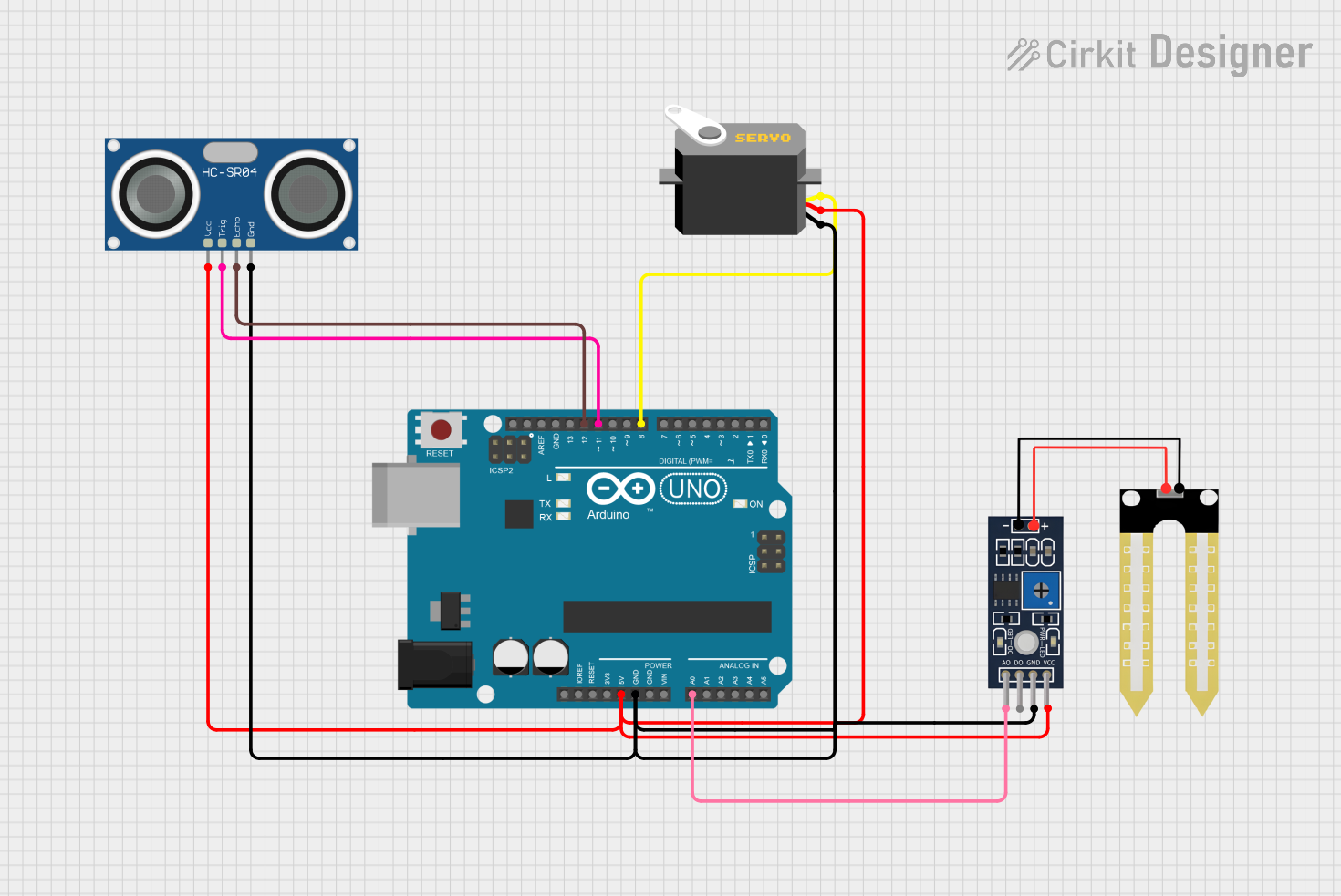
Arduino UNO Based Environmental Monitoring System with Servo and Ultrasonic Sensor

Circuit Documentation
Summary of the Circuit
This circuit integrates an Arduino UNO microcontroller with an HC-SR04 Ultrasonic Sensor, a Servo motor, and a Humidity YL-69 sensor. The Arduino UNO serves as the central processing unit, controlling the Servo motor based on the distance measurements from the HC-SR04 sensor and monitoring soil moisture levels using the Humidity YL-69 sensor. The circuit is designed to provide a 5V power supply and ground connections to all components from the Arduino UNO.
Component List
Arduino UNO
- Description: A microcontroller board based on the ATmega328P.
- Purpose: Acts as the central controller for the circuit, interfacing with sensors and controlling the Servo motor.
HC-SR04 Ultrasonic Sensor
- Description: An ultrasonic distance sensor capable of measuring distances from 2cm to 400cm.
- Purpose: Measures the distance to an object and provides this information to the Arduino UNO.
Servo
- Description: An actuator capable of precise angular positioning.
- Purpose: Receives control signals from the Arduino UNO to adjust its position based on sensor inputs.
Humidity YL-69
- Description: A soil moisture sensor that outputs an analog signal.
- Purpose: Monitors the moisture level in the soil and provides this data to the Arduino UNO.
Wiring Details
Arduino UNO
- 5V: Provides power to the Servo, Humidity YL-69 sensor, and HC-SR04 sensor.
- GND: Common ground for the Servo, Humidity YL-69 sensor, and HC-SR04 sensor.
- A0: Receives the analog signal from the Humidity YL-69 sensor.
- D12: Receives the ECHO signal from the HC-SR04 sensor.
- D11: Sends the TRIG signal to the HC-SR04 sensor.
- D8: Sends the control pulse to the Servo.
HC-SR04 Ultrasonic Sensor
- VCC: Connected to the 5V power supply from the Arduino UNO.
- TRIG: Connected to pin D11 on the Arduino UNO to receive trigger signals.
- ECHO: Connected to pin D12 on the Arduino UNO to send back the echo signal.
- GND: Connected to the common ground on the Arduino UNO.
Servo
- VCC: Connected to the 5V power supply from the Arduino UNO.
- GND: Connected to the common ground on the Arduino UNO.
- Pulse: Connected to pin D8 on the Arduino UNO to receive control pulses.
Humidity YL-69
- VCC: Connected to the 5V power supply from the Arduino UNO.
- GND: Connected to the common ground on the Arduino UNO.
- A0: Sends the analog signal to pin A0 on the Arduino UNO.
Documented Code
void setup() {
  // put your setup code here, to run once:

}

void loop() {
  // put your main code here, to run repeatedly:

}
File: sketch.ino
The provided code is a template with empty setup() and loop() functions, which are the standard structure for Arduino sketches. The setup() function is intended to contain initialization code that runs once when the microcontroller is powered on or reset. The loop() function is designed to contain the main logic of the program, which runs repeatedly as long as the microcontroller is powered.
Further implementation details should be added to these functions to initialize the pins and peripherals and to implement the control logic for reading sensors and driving the Servo motor based on the sensor inputs.