
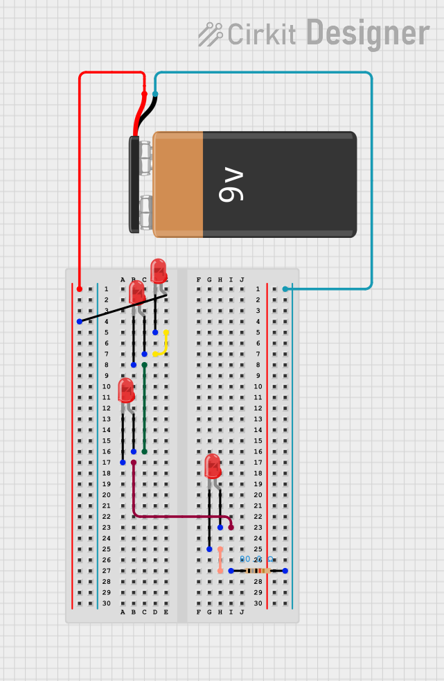
Circuit Documentation
Summary of the Circuit
The circuit described by the provided inputs is a simple LED array powered by a 9V battery with a current-limiting resistor. The array consists of four red LEDs connected in series, with a resistor placed at the end of the series to limit the current through the LEDs. The positive terminal of the battery is connected to the anode of the first LED, and the negative terminal is connected to the second terminal of the resistor, completing the circuit.
Component List
Resistor
- Description: A passive two-terminal electrical component that implements electrical resistance as a circuit element.
- Purpose: To limit the current flowing through the LEDs to prevent damage.
- Properties: 80 Ohms resistance.
LED: Two Pin (red)
- Description: A two-pin light-emitting diode that emits red light when powered.
- Purpose: To emit light when the appropriate voltage is applied across its terminals.
- Properties: Not specified.
9V Battery
- Description: A standard 9-volt battery used as the power source for the circuit.
- Purpose: To provide the necessary voltage and current to power the LEDs.
- Properties: Not specified.
Wiring Details
9V Battery
- Positive terminal (
+) connected to the anode of the first LED in the series. - Negative terminal (
-) connected to the second terminal (pin2) of the resistor.
Resistor
- One terminal (pin1) connected to the cathode of the last LED in the series.
- The other terminal (pin2) connected to the negative terminal of the 9V battery.
LED: Two Pin (red) #1
- Anode connected to the positive terminal of the 9V battery.
- Cathode connected to the anode of the second LED in the series.
LED: Two Pin (red) #2
- Anode connected to the cathode of the first LED.
- Cathode connected to the anode of the third LED in the series.
LED: Two Pin (red) #3
- Anode connected to the cathode of the second LED.
- Cathode connected to the anode of the fourth LED in the series.
LED: Two Pin (red) #4
- Anode connected to the cathode of the third LED.
- Cathode connected to one terminal (pin1) of the resistor.
Documented Code
There is no embedded code provided for this circuit as it does not include any programmable components or microcontrollers. The circuit operates purely on electrical connections without the need for software control.