
Circuit Documentation
Summary
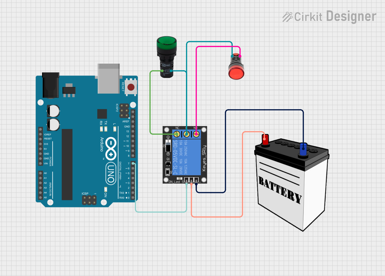
This circuit utilizes an Arduino UNO to control a 1-Channel Relay, which in turn controls a red lamp and a green pilot lamp. The relay is activated and deactivated by the Arduino, switching the lamps accordingly. When the relay is activated, the red lamp is turned on. When the relay is deactivated, the green pilot lamp is turned on.
Component List
1-Channel Relay (5V 10A)
- Pins: NC, signal, C, power, NO, ground
- Description: A relay module used to control high voltage devices with a low voltage signal.
- Purpose in Circuit: To switch between the red lamp and the green pilot lamp based on the signal from the Arduino.
12V Battery
- Pins: VCC, GND
- Description: A power source providing 12V DC.
- Purpose in Circuit: To supply power to the relay and the lamps.
Arduino UNO
- Pins: UNUSED, IOREF, Reset, 3.3V, 5V, GND, Vin, A0, A1, A2, A3, A4, A5, SCL, SDA, AREF, D13, D12, D11, D10, D9, D8, D7, D6, D5, D4, D3, D2, D1, D0
- Description: A microcontroller board based on the ATmega328P.
- Purpose in Circuit: To control the relay based on the programmed logic.
Lamp Red
- Pins: +, -
- Description: A red lamp.
- Purpose in Circuit: To indicate the relay is activated.
Pilot Lamp Green
- Pins: X1, X2
- Description: A green pilot lamp.
- Purpose in Circuit: To indicate the relay is deactivated.
Wiring Details
1-Channel Relay (5V 10A)
- NC: Connected to X1 of the Pilot Lamp Green
- signal: Connected to D7 of the Arduino UNO
- C: Connected to X2 of the Pilot Lamp Green and - of the Lamp Red
- power: Connected to VCC of the 12V Battery
- NO: Connected to + of the Lamp Red
- ground: Connected to GND of the 12V Battery
12V Battery
- VCC: Connected to power of the 1-Channel Relay
- GND: Connected to ground of the 1-Channel Relay
Arduino UNO
- D7: Connected to signal of the 1-Channel Relay
Lamp Red
- +: Connected to NO of the 1-Channel Relay
- -: Connected to X2 of the Pilot Lamp Green and C of the 1-Channel Relay
Pilot Lamp Green
- X1: Connected to NC of the 1-Channel Relay
- X2: Connected to - of the Lamp Red and C of the 1-Channel Relay
Code Documentation
/*
 * This Arduino sketch controls a 1-Channel Relay connected to pin 7 of the
 * Arduino UNO. The relay is used to control a red lamp and a green pilot lamp.
 * When the relay is activated, the red lamp is turned on. When the relay is
 * deactivated, the green pilot lamp is turned on.
 */

const int relayPin = 7; // Pin connected to the relay signal

void setup() {
  pinMode(relayPin, OUTPUT); // Set relay pin as an output
  digitalWrite(relayPin, LOW); // Initialize relay to be off
}

void loop() {
  // Example control logic
  digitalWrite(relayPin, HIGH); // Turn relay on (red lamp on)
  delay(1000); // Wait for 1 second
  digitalWrite(relayPin, LOW); // Turn relay off (green lamp on)
  delay(1000); // Wait for 1 second
}
This code initializes the relay pin as an output and sets it to LOW (relay off) in the setup() function. In the loop() function, the relay is turned on and off with a 1-second delay between each state, toggling the red and green lamps accordingly.