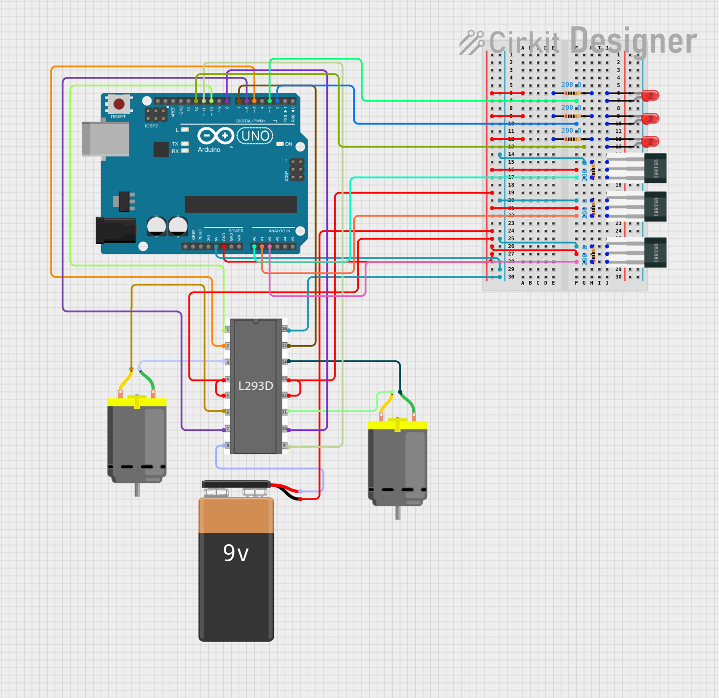
Arduino-Controlled Dual DC Motor Driver with Hall Effect Sensors and Indicator LEDs

Circuit Documentation
Summary
This circuit is designed to control two DC motors and three LEDs using an Arduino UNO microcontroller. The motors are driven by an L293D motor driver, and their operation is influenced by the state of three Hall sensors. The LEDs are used as indicators for the Hall sensors' output. The circuit is powered by a 9V battery, and it includes resistors for current limiting purposes.
Component List
Microcontroller
- Arduino UNO: A microcontroller board based on the ATmega328P, with a variety of digital and analog I/O pins.
Motor Driver
- L293D Motor Driver: A quadruple high-current half-H driver designed to provide bidirectional drive currents for motors with voltage ranges from 4.5V to 36V.
Motors
- DC Motor: Two motors that convert electrical energy into mechanical energy.
Power Supply
- 9V Battery: Provides the power required for the motors and the motor driver.
Sensors
- Hall Sensor: Three sensors used to detect magnetic fields.
LEDs
- LED: Two Pin (red): Three red LEDs used as indicators.
Resistors
- Resistor: Six resistors with a resistance of 200 Ohms, used for current limiting to the LEDs and providing a pull-up for the Hall sensors.
Wiring Details
Arduino UNO
- Digital Pin 10 to L293D Motor Driver (enable 1)
- Digital Pin 5 to L293D Motor Driver (input 1)
- Digital Pin 6 to L293D Motor Driver (input 2)
- Digital Pin 7 to L293D Motor Driver (input 4)
- Digital Pin 8 to L293D Motor Driver (input 3)
- Digital Pin 11 to L293D Motor Driver (enable 2)
- Digital Pin 12 to LED (anode)
- Digital Pin 3 to LED (anode)
- Digital Pin 2 to LED (anode)
- Analog Pin A0 to Hall Sensor (S) through a 200 Ohm resistor
- Analog Pin A1 to Hall Sensor (S) through a 200 Ohm resistor
- Analog Pin A2 to Hall Sensor (S) through a 200 Ohm resistor
- 5V to L293D Motor Driver (vss), Hall Sensors (-), and Resistors (pin2)
- GND to various components as per the net list
L293D Motor Driver
- Enable 1 and Enable 2 connected to Arduino UNO for motor control
- Input 1, Input 2, Input 3, and Input 4 connected to Arduino UNO for motor direction control
- Output 1 and Output 2 connected to one DC Motor
- Output 3 and Output 4 connected to the other DC Motor
- VS connected to the 9V Battery (+)
- VSS connected to Arduino UNO (5V)
- GND connected to the common ground net
DC Motors
- Motor 1: One pin connected to L293D Motor Driver (output 1), the other to L293D Motor Driver (output 2)
- Motor 2: One pin connected to L293D Motor Driver (output 3), the other to L293D Motor Driver (output 4)
9V Battery
- (+) to L293D Motor Driver (vs)
- (-) to the common ground net
Hall Sensors
- (+) connected to the 9V Battery (-) through a 200 Ohm resistor
- (-) connected to the common ground net
- (S) connected to the respective Arduino UNO analog pins through a 200 Ohm resistor
LEDs
- Anode connected to respective Arduino UNO digital pins
- Cathode connected to the common ground net through a 200 Ohm resistor
Resistors
- All resistors are 200 Ohms
- Connected between the Hall Sensors (S) and Arduino UNO analog pins, and between the LEDs (cathode) and common ground net
Documented Code
// Code for Arduino UNO
const int hallSensor1 = A0;
const int hallSensor2 = A1;
const int hallSensor3 = A2;
const int motor1Pin1 = 5;
const int motor1Pin2 = 6;
const int motor2Pin1 = 7;
const int motor2Pin2 = 8;
const int led1Pin = 3;
const int led2Pin = 2;
const int led3Pin = 12;

void setup() {
  pinMode(hallSensor1, INPUT);
  pinMode(hallSensor2, INPUT);
  pinMode(hallSensor3, INPUT);
  pinMode(motor1Pin1, OUTPUT);
  pinMode(motor1Pin2, OUTPUT);
  pinMode(motor2Pin1, OUTPUT);
  pinMode(motor2Pin2, OUTPUT);
  pinMode(led1Pin, OUTPUT);
  pinMode(led2Pin, OUTPUT);
  pinMode(led3Pin, OUTPUT);
}

void loop() {
  int sensor1Value = digitalRead(hallSensor1);
  int sensor2Value = digitalRead(hallSensor2);
  int sensor3Value = digitalRead(hallSensor3);

  digitalWrite(led1Pin, sensor1Value == HIGH ? HIGH : LOW);
  digitalWrite(led2Pin, sensor2Value == HIGH ? HIGH : LOW);
  digitalWrite(led3Pin, sensor3Value == HIGH ? HIGH : LOW);

  if (sensor1Value == HIGH) {
    digitalWrite(motor1Pin1, HIGH);
    digitalWrite(motor1Pin2, LOW);
  } else {
    digitalWrite(motor1Pin1, LOW);
    digitalWrite(motor1Pin2, LOW);
  }

  if (sensor2Value == HIGH) {
    digitalWrite(motor2Pin1, HIGH);
    digitalWrite(motor2Pin2, LOW);
  } else {
    digitalWrite(motor2Pin1, LOW);
    digitalWrite(motor2Pin2, LOW);
  }

  if (sensor3Value == HIGH) {
    digitalWrite(motor1Pin1, LOW);
    digitalWrite(motor1Pin2, HIGH);
  }
}
This code configures the Arduino UNO pins for input from the Hall sensors and output to the motor driver and LEDs. It reads the state of each Hall sensor and turns on the corresponding LED. Depending on the sensor readings, it controls the direction of the motors. If a Hall sensor detects a magnetic field (reads HIGH), the corresponding motor is set to rotate in one direction; otherwise, it stops. If the third sensor reads HIGH, the first motor's direction is reversed.