
Circuit Documentation
Summary
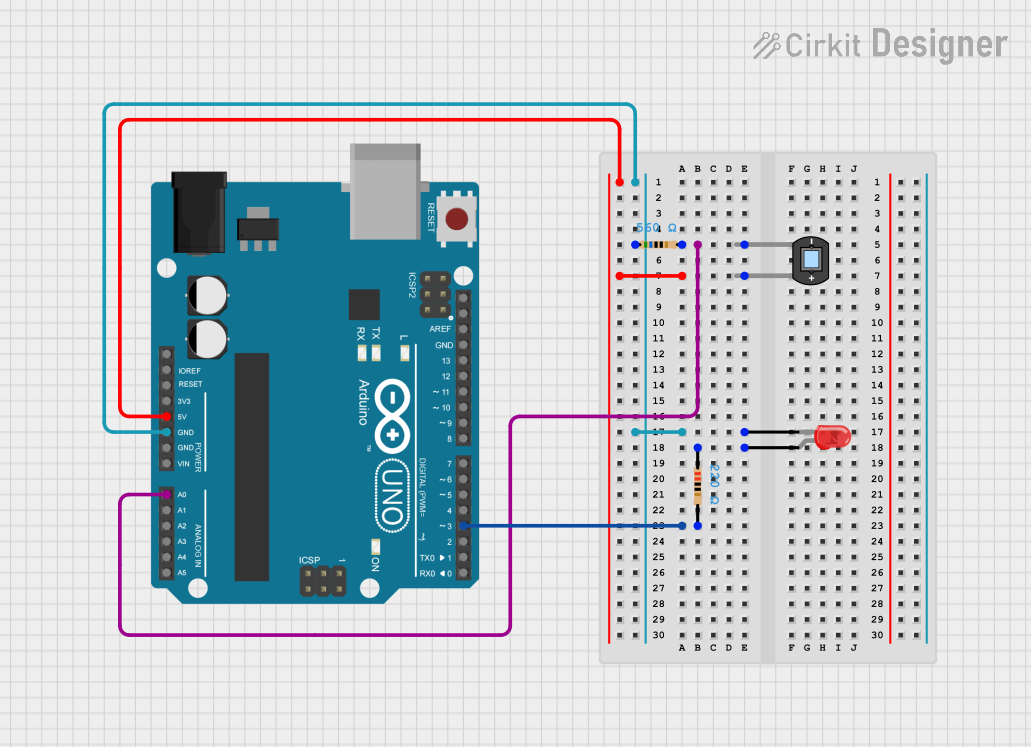
This circuit is designed to detect light levels using a photodiode and respond by lighting up an LED if the light level falls below a certain threshold. The Arduino UNO microcontroller reads the voltage from the photodiode connected to its analog input pin A0. If the light level is below the threshold value of 200, the microcontroller activates an LED connected to its digital pin D3. The photodiode is powered by the Arduino's 5V output, and the LED is connected through a 220 Ohm resistor to ground.
Component List
Arduino UNO
- Description: A microcontroller board based on the ATmega328P.
- Purpose: Acts as the central processing unit of the circuit, reading the light level from the photodiode and controlling the LED.
Photodiode
- Description: A semiconductor device that converts light into an electrical current.
- Purpose: Senses the light level in the environment and provides a corresponding voltage to the Arduino.
Resistor (560 Ohms)
- Description: A passive two-terminal electrical component that implements electrical resistance as a circuit element.
- Purpose: Limits the current flowing through the photodiode.
LED: Two Pin (red)
- Description: A two-pin light-emitting diode that emits red light.
- Purpose: Serves as a visual indicator that lights up when the light level is below the threshold.
Resistor (220 Ohms)
- Description: A passive two-terminal electrical component that implements electrical resistance as a circuit element.
- Purpose: Limits the current flowing through the LED to prevent damage.
Wiring Details
Arduino UNO
- 5V: Provides power to the photodiode.
- GND: Connected to one pin of the 560 Ohm resistor and the cathode of the LED through the 220 Ohm resistor.
- A0: Receives the voltage signal from the photodiode through the 560 Ohm resistor.
- D3: Controls the LED connected through the 220 Ohm resistor.
Photodiode
- Anode: Connected to the 5V supply from the Arduino UNO.
- Cathode: Connected to the Arduino's A0 pin through the 560 Ohm resistor.
Resistor (560 Ohms)
- Pin1: Connected to the GND on the Arduino UNO.
- Pin2: Connected to the cathode of the photodiode and the A0 pin on the Arduino UNO.
LED: Two Pin (red)
- Anode: Connected to the D3 pin on the Arduino UNO through the 220 Ohm resistor.
- Cathode: Connected to the GND on the Arduino UNO.
Resistor (220 Ohms)
- Pin1: Connected to the anode of the LED.
- Pin2: Connected to the D3 pin on the Arduino UNO.
Documented Code
/*
 * This Arduino sketch reads the voltage from a photodiode connected to A0.
 * If the light level is below a threshold (200), it lights up an LED connected
 * to digital pin D3. The photodiode is powered by the 5V pin and the LED is
 * connected through a 220 Ohm resistor to ground.
 */

const int photoPin = A0; // Photodiode connected to analog pin A0
const int ledPin = 3;    // LED connected to digital pin D3
const int threshold = 200; // Light level threshold

void setup() {
  pinMode(ledPin, OUTPUT); // Set the LED pin as an output
  pinMode(photoPin, INPUT); // Set the photodiode pin as an input
}

void loop() {
  int lightLevel = analogRead(photoPin); // Read the light level
  if (lightLevel < threshold) {
    digitalWrite(ledPin, HIGH); // Turn on the LED
  } else {
    digitalWrite(ledPin, LOW);  // Turn off the LED
  }
  delay(100); // Small delay to stabilize the reading
}
The code is written for the Arduino UNO and is saved with the filename sketch.ino. It initializes the pins, reads the light level from the photodiode, compares it to a predefined threshold, and controls the LED accordingly.