
Circuit Documentation
Summary
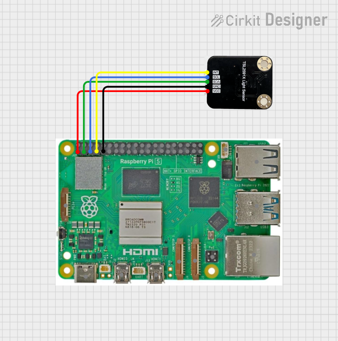
This document provides a detailed overview of a circuit that integrates a Raspberry Pi 5 with an Ambient Light Sensor. The Raspberry Pi 5 serves as the main controller, interfacing with the Ambient Light Sensor to read light intensity data. The connections between the components are established through various GPIO pins and power lines.
Component List
Raspberry Pi 5
- Description: A powerful single-board computer used for various applications including IoT, robotics, and embedded systems.
- Pins:
- Type-C
- Micro HDMI 1
- Micro HDMI 2
- Camera 1
- Camera 2
- PoE
- Fan
- PCIe
- USB 3.0
- USB 2.0
- Ethernet
- 5V
- GND
- 3.3v
- GPIO 14
- GPIO 15
- GPIO 18
- GPIO 23
- GPIO 24
- GPIO 25
- GPIO 8
- GPIO 7
- GPIO 1
- GPIO 12
- GPIO 16
- GPIO 20
- GPIO 21
- GPIO 2
- GPIO 3
- GPIO 4
- GPIO 17
- GPIO 27
- GPIO 22
- GPIO 10
- GPIO 9
- GPIO 11
- GPIO 0
- GPIO 5
- GPIO 6
- GPIO 13
- GPIO 19
- GPIO 26
Ambient Light Sensor
- Description: A sensor used to measure the intensity of ambient light.
- Pins:
- INT
- SCL
- SDA
- GND
- VCC
Wiring Details
Raspberry Pi 5
- 3.3v is connected to VCC of the Ambient Light Sensor.
- GPIO 2 is connected to SDA of the Ambient Light Sensor.
- GPIO 3 is connected to SCL of the Ambient Light Sensor.
- GPIO 4 is connected to INT of the Ambient Light Sensor.
- GND is connected to GND of the Ambient Light Sensor.
Ambient Light Sensor
- VCC is connected to 3.3v of the Raspberry Pi 5.
- SDA is connected to GPIO 2 of the Raspberry Pi 5.
- SCL is connected to GPIO 3 of the Raspberry Pi 5.
- INT is connected to GPIO 4 of the Raspberry Pi 5.
- GND is connected to GND of the Raspberry Pi 5.
Code
No code is provided for this circuit.
This document provides a comprehensive overview of the components and their interconnections in the circuit. The Raspberry Pi 5 and the Ambient Light Sensor are connected through specific GPIO pins and power lines, enabling the Raspberry Pi to read data from the sensor.